DECISION COMPUTER INTERNATIONAL CO., LTD.
TTL/IO CARD
|
Card Type |
Data acquisition |
|
Chip Set |
Signal Processing Technologies |
|
I/O Options |
Digital I/O ports (2) |
|
Data Bus |
8-bit ISA |
|
CONNECTIONS | |||
|
Function |
Label |
Function |
Label |
|
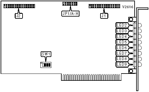
Digital I/O port 1 (see pinout below) |
J1 |
Digital I/O port 2 (see pinout below) |
J2 |
|
J1-J2 PINOUT | |||
|
Function |
Pin |
Function |
Pin |
|
DC power |
1 |
Channel 2 bit 0 |
18 |
|
Channel 0 bit 0 |
2 |
Channel 2 bit 1 |
19 |
|
Channel 0 bit 1 |
3 |
Channel 2 bit 2 |
20 |
|
Channel 0 bit 2 |
4 |
Channel 2 bit 3 |
21 |
|
Channel 0 bit 3 |
5 |
Channel 2 bit 4 |
22 |
|
Channel 0 bit 4 |
6 |
Channel 2 bit 5 |
23 |
|
Channel 0 bit 5 |
7 |
Channel 2 bit 6 |
24 |
|
Channel 0 bit 6 |
8 |
Channel 2 bit 7 |
25 |
|
Channel 0 bit 7 |
9 |
Channel 3 bit 0 |
26 |
|
Channel 1 bit 0 |
10 |
Channel 3 bit 1 |
27 |
|
Channel 1 bit 1 |
11 |
Channel 3 bit 2 |
28 |
|
Channel 1 bit 2 |
12 |
Channel 3 bit 3 |
29 |
|
Channel 1 bit 3 |
13 |
Channel 3 bit 4 |
30 |
|
Channel 1 bit 4 |
14 |
Channel 3 bit 5 |
31 |
|
Channel 1 bit 5 |
15 |
Channel 3 bit 6 |
32 |
|
Channel 1 bit 6 |
16 |
Channel 3 bit 7 |
33 |
|
Channel 1 bit 7 |
17 |
Ground |
34 |
|
Note:J2 is wired identically to J1. J1 has the signals for channels 0 through 3, and J2 has the signals for channels 4 through 7. | |||
|
BASE I/O ADDRESS | |||||
|
Setting |
SW1/1 |
SW1/2 |
SW1/3 |
SW1/4 | |
| » |
180h |
On |
On |
On |
On |
|
188h |
On |
On |
On |
Off | |
|
190h |
On |
On |
Off |
On | |
|
198h |
On |
On |
Off |
Off | |
|
1A0h |
On |
Off |
On |
On | |
|
1A8h |
On |
Off |
On |
Off | |
|
1B0h |
On |
Off |
Off |
On | |
|
1B8h |
On |
Off |
Off |
Off | |
|
1C0h |
Off |
On |
On |
On | |
|
1C8h |
Off |
On |
On |
Off | |
|
1D0h |
Off |
On |
Off |
On | |
|
1D8h |
Off |
On |
Off |
Off | |
|
1E0h |
Off |
Off |
On |
On | |
|
1E8h |
Off |
Off |
On |
Off | |
|
1F0h |
Off |
Off |
Off |
On | |
|
1F8h |
Off |
Off |
Off |
Off | |
|
LED INDICATION | ||||||||
|
Setting |
JP1/A |
JP1/B |
JP1/C |
JP1/D |
JP1/E |
JP1/F |
JP1/G |
JP1/H |
|
Channel 0 |
Closed |
Open |
Open |
Open |
Open |
Open |
Open |
Open |
|
Channel 1 |
Open |
Closed |
Open |
Open |
Open |
Open |
Open |
Open |
|
Channel 2 |
Open |
Open |
Closed |
Open |
Open |
Open |
Open |
Open |
|
Channel 3 |
Open |
Open |
Open |
Closed |
Open |
Open |
Open |
Open |
|
Channel 4 |
Open |
Open |
Open |
Open |
Closed |
Open |
Open |
Open |
|
Channel 5 |
Open |
Open |
Open |
Open |
Open |
Closed |
Open |
Open |
|
Channel 6 |
Open |
Open |
Open |
Open |
Open |
Open |
Closed |
Open |
|
Channel 7 |
Open |
Open |
Open |
Open |
Open |
Open |
Open |
Closed |
|
DIAGNOSTIC LED(S) | |||
|
LED |
Color |
Status |
Condition |
|
LED2 |
Unidentified |
On |
Bit 0 of port indicated by JP1 is active |
|
LED2 |
Unidentified |
Off |
Bit 0 of port indicated by JP1 is not active |
|
LED3 |
Unidentified |
On |
Bit 1 of port indicated by JP1 is active |
|
LED3 |
Unidentified |
Off |
Bit 1 of port indicated by JP1 is not active |
|
LED4 |
Unidentified |
On |
Bit 2 of port indicated by JP1 is active |
|
LED4 |
Unidentified |
Off |
Bit 2 of port indicated by JP1 is not active |
|
LED5 |
Unidentified |
On |
Bit 3 of port indicated by JP1 is active |
|
LED5 |
Unidentified |
Off |
Bit 3 of port indicated by JP1 is not active |
|
LED6 |
Unidentified |
On |
Bit 4 of port indicated by JP1 is active |
|
LED6 |
Unidentified |
Off |
Bit 4 of port indicated by JP1 is not active |
|
LED7 |
Unidentified |
On |
Bit 5 of port indicated by JP1 is active |
|
LED7 |
Unidentified |
Off |
Bit 5 of port indicated by JP1 is not active |
|
LED8 |
Unidentified |
On |
Bit 6 of port indicated by JP1 is active |
|
LED8 |
Unidentified |
Off |
Bit 6 of port indicated by JP1 is not active |
|
LED9 |
Unidentified |
On |
Bit 7 of port indicated by JP1 is active |
|
LED9 |
Unidentified |
Off |
Bit 7 of port indicated by JP1 is not active |