DECISION COMPUTER INTERNATIONAL CO., LTD.
PCCOM 8-PORT RJ-12 RS-232 RISC, PCCOM 8-PORT RJ-12 RS-422 RISC
|
Card Type |
Serial |
|
Chipset |
Cirrus Logic CL-CD1400 |
|
I/O Options |
Serial ports (8), interrupt daisy chain |
|
Data Bus |
16-bit ISA |
|
Card Size |
Full height, half length |
|
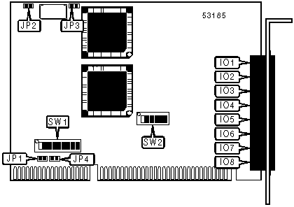
CONNECTIONS | |||
|
Function |
Label |
Function |
Label |
|
RS-232 or RS-422 serial port 1 |
IO1 |
RS-232 or RS-422 serial port 6 |
IO6 |
|
RS-232 or RS-422 serial port 2 |
IO2 |
RS-232 or RS-422 serial port 7 |
IO7 |
|
RS-232 or RS-422 serial port 3 |
IO3 |
RS-232 or RS-422 serial port 8 |
IO8 |
|
RS-232 or RS-422 serial port 4 |
IO4 |
Interrupt daisy-chain out |
JP2 |
|
RS-232 or RS-422 serial port 5 |
IO5 |
Interrupt daisy-chain in |
JP3 |
|
USER CONFIGURABLE SETTINGS | |||
|
Setting |
Label |
Position | |
| » |
Board is interrupt master |
JP1 |
Closed |
|
Board is interrupt slave |
JP1 |
Open | |
| » |
Interrupt enabled |
JP4 |
Closed |
|
Interrupt disabled |
JP4 |
Open | |
|
Note:When interrupt sharing is used, all boards should be set to interrupt enabled. When daisy-chaining is used, only the first board in the chain should be set to interrupt enabled. | |||
|
INTERRUPT SELECTION | |||||||||
|
Setting |
SW1/1 |
SW1/2 |
SW1/3 |
SW1/4 |
SW1/5 |
SW1/6 |
SW1/7 |
SW1/8 |
SW1/9 |
|
3 |
On |
Off |
Off |
Off |
Off |
Off |
Off |
Off |
Off |
|
4 |
Off |
On |
Off |
Off |
Off |
Off |
Off |
Off |
Off |
|
5 |
Off |
Off |
On |
Off |
Off |
Off |
Off |
Off |
Off |
|
6 |
Off |
Off |
Off |
On |
Off |
Off |
Off |
Off |
Off |
|
7 |
Off |
Off |
Off |
Off |
On |
Off |
Off |
Off |
Off |
|
10 |
Off |
Off |
Off |
Off |
Off |
On |
Off |
Off |
Off |
|
11 |
Off |
Off |
Off |
Off |
Off |
Off |
On |
Off |
Off |
|
12 |
Off |
Off |
Off |
Off |
Off |
Off |
Off |
On |
Off |
|
15 |
Off |
Off |
Off |
Off |
Off |
Off |
Off |
Off |
On |
|
SHARED MEMORY ADDRESS SELECTION | ||||||
|
Setting |
SW1/1 |
SW1/2 |
SW1/3 |
SW1/4 |
SW1/5 |
SW1/6 |
|
80000h |
On |
On |
On |
On |
On |
On |
|
82000h |
Off |
On |
On |
On |
On |
On |
|
84000h |
On |
Off |
On |
On |
On |
On |
|
86000h |
Off |
Off |
On |
On |
On |
On |
|
88000h |
On |
On |
Off |
On |
On |
On |
|
F6000h |
Off |
Off |
On |
Off |
Off |
Off |
|
F8000h |
On |
On |
Off |
Off |
Off |
Off |
|
FA000h |
Off |
On |
Off |
Off |
Off |
Off |
|
FC000h |
On |
Off |
Off |
Off |
Off |
Off |
|
FE000h |
Off |
Off |
Off |
Off |
Off |
Off |
|
Note: A total of 64 base address settings are available. The switches are a binary representation of the decimal memory addresses. SW1/6 is the Most Significant Bit and switch SW1/1 is the Least Significant Bit. The switches have the following decimal values: SW1/6=262,144, SW1/5=131,072, SW1/4=65,536, SW1/3=32,768, SW1/2=16,384, SW1/1=8,192. Turn off the switches and add the values of the switches that are off to 524,288 to obtain the correct memory address. (Off=1, On=0) | ||||||