DATAEXPERT CORPORATION
MIO2050
|
Card Type |
Multi-I/O card |
|
Chip Set |
Unidentified |
|
I/O Options |
Floppy drive interface, game port, IDE interface (2), parallel port, serial ports (2), 2-pin connector |
|
Hard Drives supported |
Four EIDE drives |
|
Floppy drives supported |
Two 360KB, 720KB, 1.2MB, or 1.44MB drives |
|
Data Bus |
32-bit VESA Local Bus |
|
Card Size |
Full-length, half-height |
|
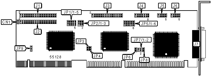
CONNECTIONS |
||||||
|
Function |
Label |
Function |
Label |
|||
|
2-pin connector - drive active LED |
CN1 |
Game port |
J4 |
|||
|
IDE interface 0 |
J1 |
Serial port 1 |
J5 |
|||
|
IDE interface 1 |
J2 |
Serial port 2 |
J6 |
|||
|
Floppy interface |
J3 |
Parallel port |
J7 |
|||
|
USER CONFIGURABLE SETTINGS |
||
|
Function |
Label |
Position |
|
í EIDE enabled |
JP1/1 |
Pins 2 & 3 |
|
EIDE disabled |
JP1/1 |
Pins 1 & 2 |
|
í 170/1F0 port test enabled |
JP1/2 |
Pins 2 & 3 |
|
1F0 port test enabled |
JP1/2 |
Pins 1 & 2 |
|
í SP1 set at 50MHz |
JP1/3 |
Pins 2 & 3 |
|
SP1 set at 33MHz |
JP1/3 |
Pins 1 & 2 |
|
í Floppy drive controller A/B change disabled |
JP2/1 |
Pins 2 & 3 |
|
Floppy drive controller A/B change enabled |
JP2/1 |
Pins 1 & 2 |
|
í Floppy drive address set at 3F7h |
JP2/2 |
Pins 2 & 3 |
|
Floppy drive address set at 377h |
JP2/2 |
Pins 1 & 2 |
|
í Floppy drive controller enabled |
JP2/3 |
Pins 2 & 3 |
|
Floppy drive controller disabled |
JP2/3 |
Pins 1 & 2 |
|
í IDE 1 IOCHRDY disabled |
JP3 |
Open |
|
IDE 1 IOCHRDY enabled |
JP3 |
Closed |
|
í IDE 0 IOCHRDY enabled |
JP4 |
Closed |
|
IDE 0 IOCHRDY disabled |
JP4 |
Open |
|
í Parallel port used for printer |
JP6 |
Closed |
|
Parallel port used for I/O peripherals |
JP6 |
Open |
|
í Game port enabled |
JP8 |
Closed |
|
Game port disabled |
JP8 |
Open |
|
í 170/1F0 port |
JP9 |
Pins 1 & 2 |
|
1F0 port only |
JP9 |
Pins 2 & 3 |
|
Note: Pins designated are in the closed position. |
||
|
PARALLEL PORT ADDRESS SELECTION |
||
|
Setting |
JP5/5 |
JP5/6 |
|
í LPT1 (378h) |
Pins 2 & 3 |
Pins 2 & 3 |
|
LPT2 (278h) |
Pins 1 & 2 |
Pins 1 & 2 |
|
LPT3 (3BCh) |
Pins 1 & 2 |
Pins 2 & 3 |
|
Disabled |
Pins 2 & 3 |
Pins 1 & 2 |
|
Note: Pins designated are in the closed position. |
||
|
SERIAL PORT 1 ADDRESS SELECTION |
||
|
Setting |
JP5/1 |
JP5/2 |
|
í COM1 (3F8h) |
Pins 2 & 3 |
Pins 2 & 3 |
|
COM3 (3E8h) |
Pins 1 & 2 |
Pins 1 & 2 |
|
Disabled |
Pins 1 & 2 |
Pins 2 & 3 |
|
Note: Pins designated are in the closed position. |
||
|
SERIAL PORT 2 ADDRESS SELECTION |
||
|
Setting |
JP5/3 |
JP5/4 |
|
í COM2 (2F8h) |
Pins 2 & 3 |
Pins 2 & 3 |
|
COM4 (2E8h) |
Pins 1 & 2 |
Pins 1 & 2 |
|
Disabled |
Pins 1 & 2 |
Pins 2 & 3 |
|
Note: Pins designated are in the closed position. |
||
|
PARALLEL PORT INTERRUPT SELECTION |
||||
|
IRQ |
JP7/1 |
JP7/2 |
||
|
í IRQ7 |
Closed |
Open |
||
|
IRQ5 |
Open |
Closed |
||
|
HARD DISK DRIVE MODE SELECTION |
|||
|
Mode |
Cycle |
JP1/4 |
JP1/5 |
|
0 |
600ns |
Pins 2 & 3 |
Pins 2 & 3 |
|
1 |
500ns |
Pins 1 & 2 |
Pins 2 & 3 |
|
2 |
400ns |
Pins 2 & 3 |
Pins 1 & 2 |
|
3 |
240ns |
Pins 1 & 2 |
Pins 1 & 2 |
|
Note: Pins designated are in the closed position. |
|||