TEKNOR INDUSTRIAL COMPUTERS, INC.
VIPER880
|
Device Type |
Single board computer |
|
Processor |
80486SX/80486DX/80486DX2/80486DX4 |
|
Processor Speed |
50(internal)/66(internal)/75(internal)/100(internal)MHz |
|
Chip Set |
VLSI 82C486 |
|
Video Chip Set |
Chips and Technology |
|
Maximum Onboard Memory |
32MB |
|
Maximum Video Memory |
1MB |
|
Cache |
128/512KB |
|
BIOS |
AMI |
|
Dimensions |
181mm x 122mm |
|
I/O Options |
Floppy drive interface, IDE interface, SCSI interface, PS/2 mouse interface, parallel port, serial ports (2), VGA port, PC/104 connectors (2) |
|
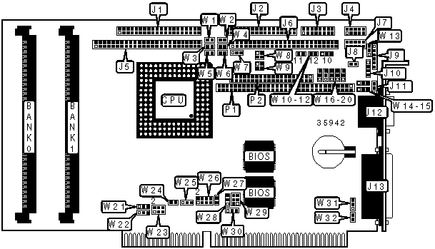
CONNECTIONS | |||
|
Purpose |
Location |
Purpose |
Location |
|
IDE interface |
J1 |
Chassis fan power |
J8 |
|
Floppy drive interface |
J2 |
Power connector |
J9 |
|
Multifunction connector |
J3 |
PS/2 mouse interface |
J10 |
|
Serial port 2 |
J4 |
VGA port |
J12 |
|
SCSI interface |
J5 |
Parallel port |
J13 |
|
Flat panel connector |
J6 |
PC/104 connector |
P1 |
|
Serial port 1 |
J7 |
PC/104 connector |
P2 |
|
USER CONFIGURABLE SETTINGS | |||
|
Function |
Label |
Position | |
|
» |
Normal boot enabled |
J11 |
Open |
|
Emergency boot enabled |
J11 |
Closed | |
|
» |
IOCHRDY signal to IDE interface disabled |
W1 |
Open |
|
IOCHRDY signal to IDE interface enabled |
W1 |
Closed | |
|
» |
Watchdog timer enabled |
W2 |
Closed |
|
Watchdog timer disabled |
W2 |
Open | |
|
» |
Power fail monitoring disabled |
W3 |
Open |
|
Power fail monitoring enabled |
W3 |
Closed | |
|
» |
Flash disk write enabled |
W4 |
Closed |
|
Flash disk write disabled |
W4 |
Open | |
|
» |
SCSI address select 340H |
W5 |
Open |
|
SCSI address select140H |
W5 |
Closed | |
|
» |
Flash BIOS write enabled |
W6 |
Closed |
|
Flash BIOS write disabled |
W6 |
Open | |
|
» |
Pixel clock polarity positive |
W7 |
Pins 1 & 2 closed |
|
Pixel clock polarity negative |
W7 |
Pins 2 & 3 closed | |
|
» |
Battery type select internal |
W10 |
Pins 1 & 2 closed |
|
Battery type select external |
W10 |
Pins 2 & 3 closed | |
|
» |
Power failure select external power fail input to pin 6 on J9 |
W13 |
Pins 1 & 2 closed |
|
Power failure select internal/external battery < 3v |
W13 |
Pins 2 & 3 closed | |
|
» |
On board video enabled |
W26/pins 1 & 2 |
Open |
|
On board video disabled |
W26/pins 1 & 2 |
Closed | |
|
» |
Factory configured – do not alter |
W26/pins 3 & 4 |
Unidentified |
|
» |
Standard mode enabled |
W26/pins 5 & 6 |
Open |
|
VT100 mode enabled |
W26/pins 5 & 6 |
Closed | |
|
» |
Serial normal mode enabled |
W26/pins 7 & 8 |
Open |
|
Serial download mode enabled |
W26/pins 7 & 8 |
Closed | |
|
» |
PS/2 mouse disabled |
W27 |
Open |
|
PS/2 mouse enabled |
W27 |
Closed | |
|
» |
Monitor type select color |
W32 |
Open |
|
Monitor type select monochrome |
W32 |
Closed | |
|
SIMM CONFIGURATION | ||
|
Size |
Bank 0 |
Bank 1 |
|
1MB |
(1) 256K x 36 |
None |
|
2MB |
(1) 512K x 36 |
None |
|
2MB |
(1) 256K x 36 |
(1) 256K x 36 |
|
3MB |
(1) 512K x 36 |
(1) 256K x 36 |
|
4MB |
(1) 1M x 36 |
None |
|
4MB |
(1) 512K x 36 |
(1) 512K x 36 |
|
5MB |
(1) 1M x 36 |
(1) 256K x 36 |
|
6MB |
(1) 1M x 36 |
(1) 512K x 36 |
|
8MB |
(1) 2M x 36 |
None |
|
SIMM CONFIGURATION | ||
|
Size |
Bank 0 |
Bank 1 |
|
8MB |
(1) 1M x 36 |
(1) 1M x 36 |
|
9MB |
(1) 2M x 36 |
(1) 256K x 36 |
|
10MB |
(1) 2M x 36 |
(1) 512K x 36 |
|
12MB |
(1) 2M x 36 |
(1) 1M x 36 |
|
16MB |
(1) 4M x 36 |
None |
|
16MB |
(1) 2M x 36 |
(1) 2M x 36 |
|
17MB |
(1) 4M x 36 |
(1) 256K x 36 |
|
18MB |
(1) 4M x 36 |
(1) 512K x 36 |
|
20MB |
(1) 4M x 36 |
(1) 1M x 36 |
|
24MB |
(1) 4M x 36 |
(1) 2M x 36 |
|
32MB |
(1) 4M x 36 |
(1) 4M x 36 |
|
CACHE CONFIGURATION |
|
Note: The location of the cache is unidentified. |
|
VIDEO MEMORY CONFIGURATION |
|
Note: The location of the video memory is unidentified. |
|
CPU SPEED SELECTION | |
|
Speed |
W29 |
|
50iMHz |
Pins 1 & 2, 3 & 4, 5 & 6 closed |
|
66iMHz |
Pins 3 & 4, 5 & 6 closed |
|
75iMHz |
Pins 1 & 2, 3 & 4, 5 & 6 closed |
|
100iMHz |
Pins 3 & 4, 5 & 6 closed |
|
CPU TYPE SELECTION | |||
|
Type |
W22 |
W24 |
W25 |
|
80486SX |
Pins 1 & 2 closed |
Open |
Open |
|
80486DX |
Pins 2 & 3 closed |
Closed |
Pins 1 & 2 closed |
|
80486DX2 |
Pins 2 & 3 closed |
Closed |
Pins 1 & 2 closed |
|
80486DX4 |
Pins 2 & 3 closed |
Closed |
Pins 1 & 2 closed |
|
ODP486 |
Pins 2 & 3 closed |
Closed |
Pins 1 & 2 closed |
|
BUSCLK SIGNAL SELECTION | |
|
Speed |
W21 |
|
16MHz |
Pins 2 & 3 closed |
|
25MHz |
Pins 1 & 2 closed |
|
33MHz |
Open |
|
DMA CHANNEL SELECTION | |||
|
Channel |
W28 |
W31 | |
| » |
None |
Open |
Open |
|
1 |
Pins 1 & 2 closed |
Pins 1 & 2 closed | |
|
3 |
Pins 2 & 3 closed |
Pins 2 & 3 closed | |
|
PARALLEL PORT INTERRUPT SELECTION | ||
|
IRQ |
W30 | |
|
None |
Open | |
|
IRQ5 |
Pins 1 & 2 closed | |
| » |
IRQ7 |
Pins 2 & 3 closed |
|
SERIAL PORT 2 SELECTION | |||||
|
Setting |
W17 |
W18 |
W19 |
W20 | |
| » |
RS-232 |
Pins 1 & 2 closed |
Pins 1 & 2 closed |
Pins 1 & 2 closed |
Pins 1 & 2 closed |
|
RS-422 |
Pins 2 & 3 closed |
Pins 2 & 3 closed |
Pins 2 & 3 closed |
Pins 2 & 3 closed | |
|
RS-485 |
Pins 2 & 3 closed |
Pins 2 & 3 closed |
Pins 2 & 3 closed |
Pins 2 & 3 closed | |
|
SERIAL PORT LOOPBACK SELECTION | |||
|
Setting |
W11 |
W12 | |
| » |
Normal |
Open |
Open |
|
Loopback |
Closed |
Closed | |
|
I/O ADDRESS SELECTION | ||
|
Address |
W23 | |
| » |
190H |
Pins 1 & 2, 3 & 4 closed |
|
290H |
Pins 1 & 2 closed | |
|
390H |
Pins 3 & 4 closed | |
|
390H |
Open | |
|
SCSI DMA CHANNEL SELECTION | |||
|
Channel |
W14 |
W15 | |
| » |
None |
Open |
Open |
|
0 |
Pins 1 & 2 closed |
Pins 2 & 3 closed | |
|
5 |
Pins 2 & 3 closed |
Pins 1 & 2 closed | |
|
SCSI INTERRUPT SELECTION | ||
|
IRQ |
W16 | |
|
10 |
Pins 1 & 2 closed | |
|
11 |
Pins 2 & 3 closed | |
| » |
None |
Open |
|
EDOUT SELECTION | |
|
Setting |
W8 |
|
EDOUT left to software |
Open |
|
EDOUT to pin 29 & ground to pin 17 |
Pins 1 & 3, 2 & 4 closed |
|
EDOUT to pin 17 & ground to pin 29 |
Pins 1 & 2, 3 & 4 closed |
|
Note: The above listed pins are located on J2. | |
|
HDOUT SELECTION | |
|
Setting |
W9 |
|
HDOUT left to software |
Open |
|
HDOUT to pin 33 & ground to pin 27 |
Pins 1 & 3, 2 & 4 closed |
|
HDOUT to pin 27 & ground to pin 33 |
Pins 1 & 2, 3 & 4 closed |
|
Note: The above listed pins are located on J2. | |