3COM CORPORATION
COURIER HST
|
Modem Type |
Data (synchronous/asynchronous) |
|
Maximum Data Rate |
9600bps |
|
Data Bus |
External |
|
Data Modulation Protocol |
Bell 103A/212A ITU-T V.22bis USR HST |
|
Error Correction/Compression |
MNP5 |
|
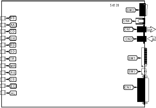
CONNECTIONS | |||
|
Purpose |
Location |
Purpose |
Location |
|
Line in |
CN1 |
DC power |
CN4 |
|
Line out |
CN2 |
Power switch |
SW2 |
|
RS-232/422 |
CN3 | ||
|
DTR SIGNAL | |
| Setting |
SW1/1 |
| » On |
DTR forced high |
| Off |
DTR normal |
|
RESULT CODES | |
| Setting |
SW1/2 |
| » Off |
Verbal result codes enabled |
| On |
Numeric result codes enabled |
|
RESULT CODES DISPLAY | |
| Setting |
SW1/3 |
| » On |
Display disabled |
| Off |
Display enabled |
|
ECHO COMMANDS DISPLAY | |
| Setting |
SW1/4 |
| » Off |
Local echo enabled |
| On |
Local echo disabled |
|
AUTO ANSWER | |
| Setting |
SW1/5 |
| » On |
Modem does not answer on first ring |
| Off |
Modem answers on first ring |
|
CARRIER DETECT | |
| Setting |
SW1/6 |
| » Off |
CD normal |
| On |
CD forced high |
|
MULTILINE PHONE INSTALLATION | |
| Setting |
SW1/7 |
| » Off |
Single phone connected |
| On |
Multiple phones connected |
|
AT COMMAND SET | |
| Setting |
SW1/8 |
| » On |
AT command set recognized |
| Off |
AT command set disabled |
|
ESCAPE CODE | |
| Setting |
SW1/9 |
| » On |
Go to command mode and display OK result code when escape character is received |
| Off |
Disconnect, go to command mode and display NO CARRIER when escape character is received |
|
USER PROFILE | |
| Setting |
SW1/10 |
| » Off |
Use stored profile |
| On |
Use factory default |
|
TX/RX PIN ASSIGNMENT | |
| Setting |
SW3 |
| » Off |
Normal operation |
| On |
Reverse TX/RX pin assignments |
|
DIAGNOSTIC LED(S) | |||
|
LED |
Color |
Status |
Condition |
|
HS |
Red |
On |
Modem is operating at 9600bps |
|
HS |
Red |
Off |
Modem is operating at slower than 9600bps |
|
AA |
Red |
On |
Auto-answer enabled |
|
AA |
Red |
Off |
Auto-answer disabled |
|
CD |
Red |
On |
Carrier signal detected |
|
CD |
Red |
Off |
Carrier signal not detected |
|
OH |
Red |
On |
Modem is off-hook |
|
OH |
Red |
Off |
Modem is on-hook |
|
RD |
Red |
Blinking |
Modem is receiving data |
|
RD |
Red |
Off |
Modem is not receiving data |
|
TD |
Red |
Blinking |
Modem is transmitting data |
|
TD |
Red |
Off |
Modem is not transmitting data |
|
TR |
Red |
On |
DTR signal is high |
|
TR |
Red |
Off |
DTR signal is low |
|
MR |
Red |
On |
Power is on |
|
MR |
Red |
Off |
Power is off |
|
MR |
Red |
Blinking |
Modem is retraining or in test mode. |
|
RS |
Red |
On |
RTS signal is high |
|
RS |
Red |
Off |
RTS signal is low |
|
CS |
Red |
On |
CTS signal is high |
|
CS |
Red |
Off |
CTS signal is low |
|
EC |
Red |
On |
Error correction enabled |
|
EC |
Red |
Off |
Error correction disabled |
|
EC |
Red |
Blinking |
Modem is retransmitting data |
|
AL |
Red |
On |
Analog loopback self test mode enabled. |
|
AL |
Red |
Off |
Normal operation |
Proprietary AT Command Set
|
BIT-MAPPED REGISTER S13 | |||
|
Format |
AT [cmds] S13=n [cmds] | ||
|
Example: |
ATS13=139 <CR> | ||
|
Default: |
0 | ||
|
Range: |
0 - 255 | ||
|
Unit: |
Bit-mapped | ||
|
Description: |
Controls DTR reset, DTR dialing, reset dialing, and MNP3. | ||
|
Bit | Value |
Function | |
|
0 | » 0 1 |
DTR normal. Reset on low DTR. | |
|
1 | » 0 1 |
Normal auto answer operation. When ring is received, enter originate and listen for answer tone. | |
|
2 | » 0 1 |
Pause 250ms before displaying result codes. Immediate result code display. | |
|
3 | » 0 1 |
DTR dialing disabled. DTR dialing enabled. | |
|
4 | » 0 1 |
Reset dialing disabled. Reset dialing enabled. | |
|
5 | » 0 |
Not used. | |
|
6 | » 0 1 |
MNP 3 enabled. MNP 3 disabled. | |
|
7 | » 0 1 |
Hardware reset disabled. Hardware reset enabled. | |
|
BIT-MAPPED REGISTER S15 | |||
|
Format: |
AT [cmds] S15=n [cmds] | ||
|
Example: |
ATS15=139 <CR> | ||
|
Default: |
0 | ||
|
Range: |
0 - 255 | ||
|
Unit: |
Bit-mapped | ||
|
Description: |
Controls HST high frequency equalization, online fallback, back channel, non-error-correcting mode buffer, MNP4, BS/DEL switch, and MNP compliance. | ||
|
Bit | Value |
Function | |
|
0 | » 0 1 |
HST high frequency equalization enabled. HST high frequency equalization disabled. | |
|
1 | » 0 1 |
Online fallback enabled. Online fallback disabled. | |
|
2 | » 0 1 |
450bps back channel enabled. 450bps back channel disabled. | |
|
3 | » 0 1 |
Non-error-correcting mode transmit buffer set to 1.5KB. Non-error-correcting mode transmit buffer set to 128 bytes. | |
|
4 | » 0 1 |
MNP 4 enabled. MNP 4 disabled. | |
|
5 | » 0 1 |
Use backspace key for delete disabled. Use backspace key for delete enabled. | |
|
6 | » 0 1 |
MNP normal. MNP adjusted for non compliant modems. | |
|
7 | » 0 1 |
Proprietary network compatibility disabled. Proprietary network compatibility enabled. | |
|
BREAK LENGTH | |
|
Type: |
Register |
|
Format: |
AT [cmds] S21=n [cmds] |
|
Example: |
ATS21=20 <CR> |
|
Default: |
10 |
|
Range: |
Unidentified |
|
Unit: |
10 ms |
|
Description: |
Sets the length of Error correction mode breaks sent from DCE to DTE. |
|
BREAK TYPE | |
|
Type: |
Configuration |
|
Format: |
AT [cmds] &Yn [cmds] |
|
Example: |
AT &Y0 <CR> |
|
Description: |
Configures action of break signal. |
| Command |
Function |
| &Y0 |
Break empties buffer. |
| » &Y1 |
Break empties buffer and is sent immediately. |
| &Y2 |
Break does not empty buffer and is sent immediately. |
| &Y3 |
Break does not empty buffer and is sent with transmitted data. |
|
CONNECTION SPEED UPPER LIMIT | |
|
Type: |
Configuration |
|
Format: |
AT [cmds] &Nn [cmds] |
|
Example: |
AT &N1 DT555-1212 <CR> |
|
Description: |
Sets required connection speed if &U is set to 0. Otherwise, sets fastest allowed connection speed. |
| Command |
Function |
| » &N0 |
Variable. |
| &N1 |
300bps |
| &N2 |
1200bps |
| &N3 |
2400bps |
| &N4 |
4800bps |
| &N5 |
7200bps |
| &N6 |
9600bps |
|
DISCONNECT DISPLAY | |
|
Type: |
Immediate |
|
Format: |
AT [cmds] S17? [cmds] |
|
Example: |
ATS17? <CR> |
|
Default: |
Read only |
|
Range: |
1-6, 254, 255 |
|
Description: |
Displays the reason for a disconnect during error correcting mode. |
|
Value |
Meaning |
|
S17=1 |
Received data different than requested. |
|
S17=2 |
Incompatible MNP protocol. |
|
S17=3 |
Connection request parameters unknown. |
|
S17=4 |
Remote modem retry timeout. |
|
S17=5 |
Inactivity timeout. |
|
S17=6 |
Destination user not found. |
|
S17=254 |
Peer protocol error. |
|
S17=255 |
User initiated disconnect. |
|
ERROR CORRECTION MODE | |
|
Type: |
Configuration |
|
Format: |
AT [cmds] &Mn [cmds] |
|
Example: |
AT &M1 %C1 <CR> |
|
Description: |
Selects active error correction protocols. |
| Command |
Function |
| &M0 |
Normal mode only. |
| » &M4 |
Auto-detect mode. |
| &M5 |
ARQ mode only. |
|
EXTENDED RESULT CODES | |
|
Type: |
Configuration |
|
Format: |
AT [cmds] &An [cmds] |
|
Example: |
AT &A1 %C1 <CR> |
|
Description: |
Selects extended result codes. |
| Command |
Function |
| &A0 |
Extended result codes disabled. |
| » &A1 |
ARQ result codes enabled. |
|
FLOW CONTROL CHARACTER - XOFF | |
|
Type: |
Register |
|
Format: |
AT [cmds] S23=n [cmds] |
|
Example: |
ATS23=20 <CR> |
|
Default: |
19 |
|
Range: |
11-127 |
|
Unit: |
ASCII |
|
Description: |
Sets the character used to represent XOFF. |
|
FLOW CONTROL CHARACTER - XON | |
|
Type: |
Register |
|
Format: |
AT [cmds] S22=n [cmds] |
|
Example: |
ATS22=20 <CR> |
|
Default: |
17 |
|
Range: |
11-127 |
|
Unit: |
ASCII |
|
Description: |
Sets the character used to represent XON. |
|
FLOW CONTROL PASSTHROUGH | |
|
Type: |
Configuration |
|
Format: |
AT [cmds] &In [cmds] |
|
Example: |
AT &I0 &W <CR> |
|
Description: |
Allows modem to act on, then transmit XON/XOFF characters. |
| Command |
Function |
| » &I0 |
Software flow control disabled. |
| &I1 |
XON/XOFF passthrough enabled. |
| &I2 |
XON/XOFF passthrough disabled. |
| &I3 |
Hewlett-Packard host mode. |
| &I4 |
Hewlett-Packard Terminal mode. |
| &I5 |
XON/XOFF passthrough for non error correction mode enabled. |
|
FLOW CONTROL TYPE | |
|
Type: |
Configuration |
|
Format: |
AT [cmds] &Hn [cmds] |
|
Example: |
AT &H0 A <CR> |
|
Description: |
Sets type of flow control used by modem. |
| Command |
Function |
| » &H0 |
Flow control disabled. |
| &H1 |
CTS/RTS flow control enabled. |
| &H2 |
XON/XOFF flow control enabled. |
| &H3 |
CTS/RTS and XON/XOFF flow control enabled. |
|
PAUSE | |
|
Type: |
Configuration |
|
Format: |
AT [cmds] / [cmds] |
|
Example: |
AT /// &W <CR> |
|
Description: |
125ms pause for each /. |
|
HELP SCREENS | |
|
Type: |
Immediate |
|
Format: |
AT <prefix>$ |
|
Example: |
AT &$ <CR> |
|
Description: |
Shows command help screens for all commands beginning with the given prefix, or no prefix if none is given. |
|
Command |
Function |
|
$ |
Shows ATx help screen. |
|
&$ |
Shows AT& help screen. |
|
D$ |
Shows ATDx help screen. |
|
S$ |
Shows S-register help screen. |
|
INACTIVITY TIMER | |
|
Type: |
Register |
|
Format: |
AT [cmds] S19=n [cmds] |
|
Example: |
ATS19=20 <CR> |
|
Default: |
0 |
|
Range: |
Unidentified |
|
Unit: |
1 minute |
|
Description: |
Sets the length of time that the modem does not receive information before it disconnects. |
|
NO CARRIER DISPLAY | |
|
Type: |
Immediate |
|
Format: |
AT [cmds] S20? [cmds] |
|
Example: |
ATS20? <CR> |
|
Default: |
Read only |
|
Range: |
0-7 |
|
Description: |
Displays the reason for a NO CARRIER result code.. |
|
Value |
Meaning |
|
S20=0 |
Key press abort. |
|
S20=1 |
DTR low. |
|
S20=2 |
Escape code sent. |
|
S20=3 |
Connection broken. |
|
S20=4 |
Inactivity timeout. |
|
S20=5 |
Automatic hangup with error correction incompatibility . |
|
S20=6 |
Error correction retry timeout. |
|
S20=7 |
Error correction received disconnect. |
|
REGISTER S18 |
|
Note: This register is reserved and should not be changed. |
|
REPEAT COMMAND STRING | |
|
Type: |
Configuration |
|
Format: |
AT [cmds] > [cmds] |
|
Example: |
AT *D1 > #E1 <CR> |
|
Description: |
Causes modem to repeat command string until a keyboard key is pressed. |
|
REPORT INFORMATION | |
|
Type: |
Immediate |
|
Format: |
AT [cmds] In [cmds] |
|
Example: |
AT I1 O <CR> |
|
Description: |
Displays modem properties. |
|
Command |
Function |
|
I0 |
Reports product code. |
|
I1 |
Reports ROM checksum result. |
|
I2 |
Reports RAM checksum result. |
|
I3 |
Reports call duration. |
|
I4 |
Reports current command settings. |
|
I5 |
Reports current NVRAM settings. |
|
I6 |
Reports current connection’s statistics. |
|
I7 |
Reports configuration. |
|
TEST MODES | |
|
Type: |
Register |
|
Format: |
AT [cmds] S16=n [cmds] |
|
Example: |
ATS16=0 <CR> |
|
Description: |
Controls analog loopback pattern and dial tests |
| Command |
Function |
| » S16=0 |
Testing disabled. |
| S16=1 |
Analog loopback test enabled. |
| S16=2 |
Dial test enabled. |
| S16=4 |
Test pattern enabled. |
| S16=5 |
Analog loopback with test pattern enabled. |
|
TIME DISPLAY | |
|
Type: |
Immediate |
|
Format: |
AT [cmds] Kn [cmds] |
|
Example: |
AT K1 *L2 #E1<CR> |
|
Description: |
Displays the current call time or clock time. |
| Command |
Function |
| » K0 |
Display length of last call. |
| K1 |
Display actual time. |