DATA TECHNOLOGY CORPORATION
DTC5250CX
|
| |
|
Data bus: |
8-bit, ISA |
|
Size: |
Full-length, full-height card |
|
Hard drive supported: |
Two MFM ST506/412 drives |
|
Floppy drives supported: |
Four 360KB, 720KB, 1.2MB, or 1.44MB drives |
|
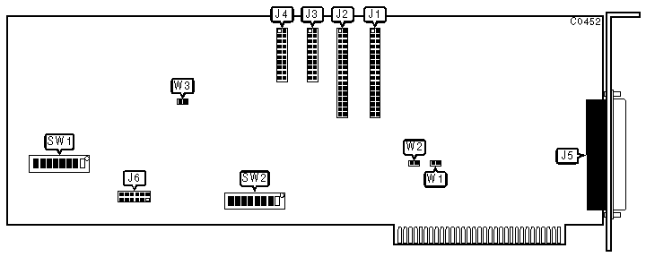
CONNECTIONS | |
|
Function |
Location |
|
34-pin control cable connector-floppy drive |
J1 |
|
34-pin control cable connector-hard drive |
J2 |
|
20-pin data cable connector - drive 0 |
J3 |
|
20-pin data cable connector - drive 1 |
J4 |
|
34-pin floppy drive cable connector - external |
J5 |
|
USER CONFIGURABLE SETTINGS | |||
|
Function |
Location |
Setting | |
| » |
Floppy drive enabled |
J6/jumper 3 |
open |
|
Floppy drive disabled |
J6/jumper 3 |
closed | |
| » |
Floppy drive B: 96 tracks per inch density enabled |
J6/jumper 6 |
closed |
|
Floppy drive B: 48 tracks per inch density enabled |
J6/jumper 6 |
open | |
| » |
Floppy drive A: 96 tracks per inch density enabled |
J6/jumper 7 |
closed |
|
Floppy drive A: 48 tracks per inch density enabled |
J6/jumper 7 |
open | |
|
USER CONFIGURABLE SETTINGS | |||
|
Function |
Location |
Setting | |
| » |
Floppy drive port address is 3F0-3F7h |
SW2/switch 1 |
off |
|
Floppy drive port address is 370-377h |
SW2/switch 1 |
on | |
| » |
BIOS enabled |
SW2/switch 3 |
on |
|
BIOS disabled |
SW2/switch 3 |
off | |
| » |
BIOS size 16KB |
SW2/switch 4 |
on |
|
BIOS size 8KB |
SW2/switch 4 |
off | |
|
DRIVE TYPE SETTINGS - SW1/SWITCHES 1-8 |
|
For settings of SW1 see drive type settings table in document C0061 |
|
BIOS ADDRESS | |||||
|
Address |
SW2/switch 5 |
SW2/switch 6 |
SW2/switch 7 |
SW2/switch 8 | |
| » |
C800h |
on |
off |
on |
on |
|
D800h |
on |
off |
off |
on | |
|
E800h |
on |
off |
on |
off | |
|
MISCELLANEOUS TECHNICAL NOTES |
|
SW2/switch 2 is not used. If QIT01B1 EPROM is installed, jumper W1 must be closed, jumpers W2 and W3 must be open. The functions of J6/jumpers 1, 2, 4, 5, and 8 are undocumented. |