WESTERN DIGITAL CORPORATION
WD1003V-SR1/SR2, WD1006V-SR1/SR2
Replaces WD1003-RAH/RA2 & WD1006-RAH/RA2 respectively
|
Data bus: |
16-bit, ISA |
|
Size: |
Full-length, full-height card |
|
Hard drive supported: |
Two RLL ST506/412 drives |
|
Floppy drives supported: |
Two 360KB, 720KB, 1.2MB, or 1.44MB drives |
|
Maximum heads/cyl.: |
16 heads 2048 cylinders |
|
Options |
Feature F301R has an optional ROM BIOS with shadow Ram which enables controller to interface with all types of ESDI drives bypassing the systems ROM BIOS drive type tables. Feature F300R does not include ROM BIOS option and system ROM BIOS must contain appropriate drive parameters. |
|
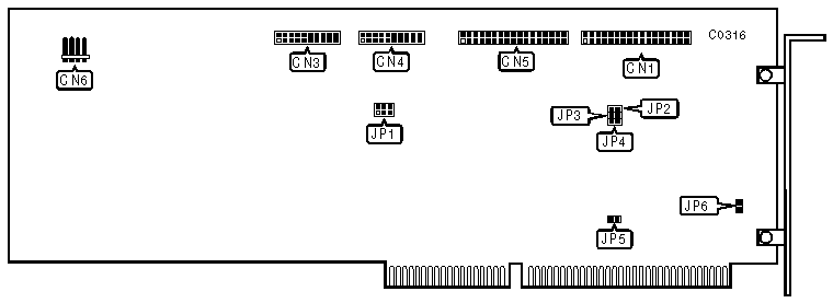
CONNECTIONS | |
|
Function |
Location |
|
34-pin data cable connector-floppy drive |
CN1 |
|
20-pin data cable connector-drive 1 |
CN3 |
|
20-pin data cable connector-drive 0 |
CN4 |
|
34-pin control cable connector-hard drive |
CN5 |
|
4-pin connector-drive active LED |
CN6 |
|
USER CONFIGURABLE SETTINGS | |||
|
Function |
Location |
Setting | |
| » |
Hard drives in latched mode |
JP1/jumper 1 |
open |
|
Hard drives in non-latched mode |
JP1/jumper 1 |
closed | |
| » |
4 byte ECC |
JP1/jumper 2 |
open |
|
7 byte ECC |
JP1/jumper 2 |
closed | |
| » |
Caching enabled |
JP1/jumper 3 |
open |
|
Caching disabled |
JP1/jumper 3 |
closed | |
| » |
BIOS enabled |
JP2 |
open |
|
BIOS disabled |
JP2 |
closed | |
| » |
Hard drive port address is 1F0-1F7h |
JP3 |
open |
|
Hard drive port address is 170-177h |
JP3 |
closed | |
| » |
Floppy drive port address is 3F0-3F7h |
JP4 |
open |
|
Floppy drive port address is 370-377h |
JP4 |
closed | |
| » |
Single speed floppy drives supported |
JP5 |
open |
|
Dual speed floppy drives supported |
JP5 |
closed | |
| » |
Bracket ground option disabled |
JP6 |
open |
|
Bracket to board ground connected |
JP6 |
closed | |
|
MISCELLANEOUS TECHNICAL NOTES |
|
Not all jumpers are installed. You must solder those that are not present. Do not combine single- and dual-speed floppy drives on the same controller card. This controller has a built-in low-level format program. To enter the progam run the DEBUG utility supplied with DOS and at the prompt enter: G=CC00:5. |