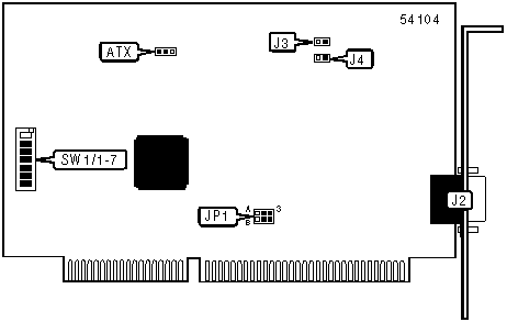
B & B ELECTRONICS
ATRWDT, ATXWDT
|
Card Type |
Watchdog timer card |
|
Chip Set |
None |
|
Maximum Onboard Memory |
Unidentified |
|
I/O Options |
Serial port |
|
Hard Drives supported |
None |
|
Floppy drives supported |
None |
|
Data Bus |
16-bit ISA |
|
Card Size |
Full-length |

|
CONNECTIONS | |||
|
Function |
Label |
Function |
Label |
|
9-pin serial port |
J2 |
Reset button connector |
J4 |
|
Motherboard reset connector |
J3 |
ATX power supply connector |
ATX |
|
USER CONFIGURABLE SETTINGS | ||
|
Function |
Label |
Position |
|
Normal relay enabled |
JP1/A-B |
Pins 1 & 2 closed |
|
Timer relay enabled |
JP1/A-B |
Pins 2 & 3 closed |
|
Note: If normal relay is enabled, the relay will discharge normally and will energize after the timeout is reached. If timer relay is enabled, the relay will be energized while the timer is running and discharge after the timeout is reached, disabled, or the power is turned off. | ||
|
BASE I/O ADDRESS SELECTION | |||||||
|
Setting |
SW1/1 |
SW1/2 |
SW1/3 |
SW1/4 |
SW1/5 |
SW1/6 |
SW1/7 |
|
000h |
On |
On |
On |
On |
On |
On |
On |
|
008h |
Off |
On |
On |
On |
On |
On |
On |
|
010h |
On |
Off |
On |
On |
On |
On |
On |
|
018h |
Off |
Off |
On |
On |
On |
On |
On |
|
020h |
On |
On |
Off |
On |
On |
On |
On |
|
3D8h |
Off |
Off |
On |
Off |
Off |
Off |
Off |
|
3E0h |
On |
On |
Off |
Off |
Off |
Off |
Off |
|
3E8h |
Off |
On |
Off |
Off |
Off |
Off |
Off |
|
3F0h |
On |
Off |
Off |
Off |
Off |
Off |
Off |
|
3F8h |
Off |
Off |
Off |
Off |
Off |
Off |
Off |
|
Note: A total of 128 base address settings are available. The switches are a binary representation of the decimal memory addresses. SW1/7 is the Most Significant Bit and switch SW1/1 is the Least Significant Bit. The switches have the following decimal values: SW1/7=512, SW1/6=256, SW1/5=128, SW1/4=64, SW1/3=32, SW1/2=16, SW1/1=8. Turn off the switches and add the values of the switches to obtain the correct memory address. (Off=1, On=0) | |||||||
|
MISCELLANEOUS TECHNICAL NOTES |
|
To enable the ATR version of the watchdog timer card to reboot the main board, they must be connected. The mother board reset connector on the watchdog timer card can be connected to the reset pins on the main board or the reset button connector of the watchdog timer card can be connected to the jumper wires of the main board’s reset switch. |