DIGI INTERNATIONAL, INC.
DIGICHANNEL PC/8
|
Card Type |
Serial |
|
Chip Set |
Unidentified |
|
I/O Options |
Serial ports (8) |
|
Data Bus |
8-bit ISA |
|
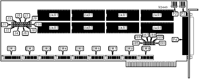
CONNECTIONS | |||
|
Function |
Label |
Function |
Label |
|
Odd-interrupt daisy chain connector |
P2 |
Serial ports via DB-78 connector |
P4 |
|
Even-interrupt daisy chain connector |
P3 | ||
|
Note:Standard DB-25 or RJ-45 serial ports are provided on an included adapter cable. See the daisy chain configuration table for more information about P2 and P3. | |||
|
USER CONFIGURABLE SETTINGS | |||
|
Setting |
Label |
Position | |
| » |
Port 1 uses interrupt table 1 (odd interrupts) |
J1 |
Pins 1 & 2 closed |
|
Port 1 uses interrupt table 2 (even interrupts) |
J1 |
Pins 2 & 3 closed | |
| » |
Port 2 uses interrupt table 1 |
J2 |
Pins 1 & 2 closed |
|
Port 2 uses interrupt table 2 |
J2 |
Pins 2 & 3 closed | |
| » |
Port 3 uses interrupt table 1 |
J3 |
Pins 1 & 2 closed |
|
Port 3 uses interrupt table 2 |
J3 |
Pins 2 & 3 closed | |
| » |
Port 4 uses interrupt table 1 |
J4 |
Pins 1 & 2 closed |
|
Port 4 uses interrupt table 2 |
J4 |
Pins 2 & 3 closed | |
| » |
Port 5 uses interrupt table 1 |
J5 |
Pins 1 & 2 closed |
|
Port 5 uses interrupt table 2 |
J5 |
Pins 2 & 3 closed | |
| » |
Port 6 uses interrupt table 1 |
J6 |
Pins 1 & 2 closed |
|
Port 6 uses interrupt table 2 |
J6 |
Pins 2 & 3 closed | |
| » |
Port 7 uses interrupt table 1 |
J7 |
Pins 1 & 2 closed |
|
Port 7 uses interrupt table 2 |
J7 |
Pins 2 & 3 closed | |
| » |
Port 8 uses interrupt table 1 |
J8 |
Pins 1 & 2 closed |
|
Port 8 uses interrupt table 2 |
J8 |
Pins 2 & 3 closed | |
| » |
Factory configured - do not alter |
SW1/8 |
On |
| » |
Factory configured - do not alter |
SW1/9 |
On |
|
USER CONFIGURABLE SETTINGS (CON’T) | |||
|
Setting |
Label |
Position | |
| » |
Port 1 enabled |
SW2/8 |
On |
|
Port 1 disabled |
SW2/8 |
Off | |
| » |
Port 2 enabled |
SW3/8 |
On |
|
Port 2 disabled |
SW3/8 |
Off | |
| » |
Port 3 enabled |
SW4/8 |
On |
|
Port 3 disabled |
SW4/8 |
Off | |
| » |
Port 4 enabled |
SW5/8 |
On |
|
Port 4 disabled |
SW5/8 |
Off | |
| » |
Port 5 enabled |
SW6/8 |
On |
|
Port 5 disabled |
SW6/8 |
Off | |
| » |
Port 6 enabled |
SW7/8 |
On |
|
Port 6 disabled |
SW7/8 |
Off | |
| » |
Port 7 enabled |
SW8/8 |
On |
|
Port 7 disabled |
SW8/8 |
Off | |
| » |
Port 8 enabled |
SW9/8 |
On |
|
Port 8 disabled |
SW9/8 |
Off | |
|
BOARD NUMBER | ||
|
Setting |
J9 |
J10 |
|
0 |
Pins 2 & 3 closed |
Pins 2 & 3 closed |
|
1 |
Pins 2 & 3 closed |
Pins 1 & 2 closed |
|
2 |
Pins 1 & 2 closed |
Pins 2 & 3 closed |
|
3 |
Pins 1 & 2 closed |
Pins 1 & 2 closed |
|
STATUS REGISTER ADDRESS | ||||||||
|
Setting |
SW1/1 |
SW1/2 |
SW1/3 |
SW1/4 |
SW1/5 |
SW1/6 |
SW1/7 |
SW1/10 |
|
000h |
On |
On |
On |
On |
On |
On |
On |
On |
|
008h |
On |
On |
On |
On |
On |
On |
Off |
On |
|
010h |
On |
On |
On |
On |
On |
Off |
On |
On |
|
018h |
On |
On |
On |
On |
On |
Off |
Off |
On |
|
020h |
On |
On |
On |
On |
Off |
On |
On |
On |
|
3D8h |
Off |
Off |
Off |
Off |
On |
Off |
Off |
On |
|
3E0h |
Off |
Off |
Off |
Off |
Off |
On |
On |
On |
|
3E8h |
Off |
Off |
Off |
Off |
Off |
On |
Off |
On |
|
3F0h |
Off |
Off |
Off |
Off |
Off |
Off |
On |
On |
|
3F8h |
Off |
Off |
Off |
Off |
Off |
Off |
Off |
On |
|
Disabled |
Off |
Off |
Off |
Off |
Off |
Off |
Off |
Off |
|
Note: A total of 128 base address settings are available. The switches are a binary representation of the decimal memory addresses. SW1/1 is the Most Significant Bit and switch SW1/7 is the Least Significant Bit. The switches have the following decimal values: SW1/1=512, SW1/2=256, SW1/3=128, SW1/4=64, SW1/5=32, SW1/6=16, SW1/7=8. Turn off the switches and add the values of the switches that are off to obtain the correct memory address. (Off=1, On=0) SW1/10 must always be on. | ||||||||
|
PORT ADDRESSES | |||||||
|
Setting |
SW2/1 |
SW2/2 |
SW2/3 |
SW2/4 |
SW2/5 |
SW2/6 |
SW2/7 |
|
000h |
On |
On |
On |
On |
On |
On |
On |
|
008h |
On |
On |
On |
On |
On |
On |
Off |
|
010h |
On |
On |
On |
On |
On |
Off |
On |
|
018h |
On |
On |
On |
On |
On |
Off |
Off |
|
020h |
On |
On |
On |
On |
Off |
On |
On |
|
3D8h |
Off |
Off |
Off |
Off |
On |
Off |
Off |
|
3E0h |
Off |
Off |
Off |
Off |
Off |
On |
On |
|
3E8h |
Off |
Off |
Off |
Off |
Off |
On |
Off |
|
3F0h |
Off |
Off |
Off |
Off |
Off |
Off |
On |
|
3F8h |
Off |
Off |
Off |
Off |
Off |
Off |
Off |
|
Note:The function of switches SW3-SW5 are identical to the function of SW2. The function of SW2 is to configure port 1. The functions of switches SW3 through SW5 are to configure ports 2 through 4 respectively. A total of 128 base address settings are available. The switches are a binary representation of the decimal memory addresses. SWx/1 is the Most Significant Bit and switch SWx/7 is the Least Significant Bit. The switches have the following decimal values: SWx/1=512, SWx/2=256, SWx/3=128, SWx/4=64, SWx/5=32, SWx/6=16, SWx/7=8. Turn off the switches and add the values of the switches that are off to obtain the correct memory address. (Off=1, On=0) | |||||||
|
INTERRUPT (TABLE 1) | ||||||
|
Setting |
J85 |
J86 |
J87 |
J88 |
J89 |
J90 |
|
IRQ3 |
Closed |
Open |
Open |
Open |
Open |
Open |
|
IRQ5 |
Open |
Closed |
Open |
Open |
Open |
Open |
|
IRQ7 |
Open |
Open |
Closed |
Open |
Open |
Open |
|
Disabled |
Open |
Open |
Open |
Open |
Open |
Open |
|
INTERRUPT (TABLE 2) | ||||||
|
Setting |
J85 |
J86 |
J87 |
J88 |
J89 |
J90 |
|
IRQ2 |
Open |
Open |
Open |
Open |
Open |
Closed |
|
IRQ4 |
Open |
Open |
Open |
Open |
Closed |
Open |
|
IRQ6 |
Open |
Open |
Open |
Closed |
Open |
Open |
|
Disabled |
Open |
Open |
Open |
Open |
Open |
Open |
|
DAISY CHAIN CONFIGURATION | ||
|
Setting |
P2 |
P3 |
|
No daisy chain |
Pins 2 & 3 closed |
Pins 2 & 3 closed |
|
Board is set to odd interrupt |
Connected to P2 on next board |
Pins 2 & 3 closed |
|
Board is set to even interrupt |
Pins 2 & 3 closed |
Connected to P3 on next board |
|
Note:When using the daisy-chain connectors, the board may only use one interrupt. Up to four boards may be daisy-chained. Daisy-chaining boards to operate as one unit will only function under MS-DOS and compatible operating systems. | ||
|
MISCELLANEOUS TECHNICAL NOTE |
|
When using non-MS-DOS compatible operating systems, each board should be configured as a separate unit with different interrupts and I/O addresses. |