ELETECH ENTERPRISE CO., LTD.
V-LINK/2C (VP-892CPM)
|
Card Type |
Voice card |
|
Chip Set |
Unidentified |
|
Maximum Onboard Memory |
N/A |
|
I/O Options |
Line1, line 2, microphone in, tape in, speaker out |
|
Hard Drives supported |
None |
|
Floppy drives supported |
None |
|
Data Bus |
16-bit ISA |
|
Card Size |
Three-quarter-length, full-height |
|
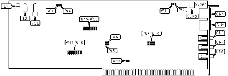
CONNECTIONS | |||
|
Function |
Label |
Function |
Label |
|
Line 2 |
CN1 |
Speaker out |
CN5 |
|
Line 1 |
CN2 |
Unidentified |
SENS |
|
Microphone in |
CN3 |
Volume |
VOL |
|
Tape in |
CN4 | ||
|
USER CONFIGURABLE SETTINGS | |||
|
Function |
Label |
Position | |
| » |
1/2 make/break ratio for pulse dialing on line 1 enabled |
W5 |
Closed |
|
2/3 make/break ratio for pulse dialing on line 1 enabled |
W5 |
Open | |
| » |
1/2 make/break ratio for pulse dialing on line 2 enabled |
W6 |
Closed |
|
2/3 make/break ratio for pulse dialing on line 2 enabled |
W6 |
Open | |
| » |
Sampling rate for both lines is 32 Kbps |
W11 |
Closed |
|
Sampling rate for both lines is 44.5 Kbps |
W11 |
Open | |
| » |
Factory configured - do not alter |
W19 |
Unidentified |
| » |
Factory configured - do not alter |
W20 |
Unidentified |
| » |
Factory configured - do not alter |
W21 |
Unidentified |
| » |
Factory configured - do not alter |
W22 |
Unidentified |
| » |
Factory configured - do not alter |
W23 |
Unidentified |
| » |
Factory configured - do not alter |
W24 |
Unidentified |
| » |
Factory configured - do not alter |
W25 |
Unidentified |
|
MICROPHONE /TAPE INPUT SELECTION | |||
|
Setting |
W1 |
W2 | |
| » |
Line 1 |
Closed |
Open |
|
Line 2 |
Open |
Closed | |
|
SPEAKER OUTPUT SELECTION | |||
|
Setting |
W3 |
W4 | |
| » |
Line 1 |
Closed |
Open |
|
Line 2 |
Open |
Closed | |
|
Note:This option is usually set according to microphone/tape input selection since the speaker is usually used to monitor the recording of messages from a tape player. | |||
|
LINE 1 BASE I/O ADDRESS AND INTERRUPT SELECTION | |||
|
IRQ |
I/O Address |
W7 |
W8 |
|
2 |
238h |
Closed |
Closed |
|
3 |
270h |
Open |
Closed |
|
5 |
230h |
Closed |
Open |
|
7 |
278h |
Open |
Open |
|
LINE 2 BASE I/O ADDRESS AND INTERRUPT SELECTION | |||
|
IRQ |
I/O Address |
W9 |
W10 |
|
10 |
310h |
Closed |
Closed |
|
11 |
318h |
Closed |
Open |
|
12 |
320h |
Open |
Closed |
|
15 |
328h |
Open |
Open |
|
NSP TIMING SELECTION | |||||||
|
Setting |
W12 |
W13 |
W14 |
W15 |
W16 |
W17 |
W18 |
|
1.56 |
Off |
On |
Off |
Off |
Off |
Off |
Off |
|
1.87 |
Off |
Off |
On |
Off |
Off |
Off |
Off |
|
2.18 |
Off |
Off |
Off |
On |
Off |
Off |
Off |
|
2.50 |
Off |
Off |
Off |
Off |
On |
Off |
Off |
|
2.81 |
Off |
Off |
Off |
Off |
Off |
On |
Off |
|
3.12 |
Off |
Off |
Off |
Off |
Off |
Off |
On |
|
1.81 |
On |
On |
Off |
Off |
Off |
Off |
Off |
|
2.19 |
On |
Off |
On |
Off |
Off |
Off |
Off |
|
2.56 |
On |
Off |
Off |
On |
Off |
Off |
Off |
|
2.94 |
On |
Off |
Off |
Off |
On |
Off |
Off |
|
3.31 |
On |
Off |
Off |
Off |
Off |
On |
Off |
|
3.69 |
On |
Off |
Off |
Off |
Off |
Off |
On |
|
VR1, VR2 SELECTION | ||
|
Label |
Status |
Condition |
|
VR1 |
Turn clockwise |
Amplify microphone input signal |
|
VR2 |
Turn clockwise |
Increase speaker output volume |
|
Note:Location of VR1 and VR2 is unidentified. | ||
|
DIAGNOSTIC LED(S) | ||
|
LED |
Status |
Condition |
|
L1 |
On |
Hookswitch of line 1 is off-hook |
|
L1 |
Off |
Hookswitch of line 1 is on-hook |
|
L2 |
On |
Hookswitch of line 2 is off-hook |
|
L2 |
Off |
Hookswitch of line 2 is on-hook |