AMERICAN MEGATRENDS, INC.
AMI-386XT SERIES-6
|
Processor |
80386DX |
|
Processor Speed |
8/16/20/25MHz |
|
Chip Set |
AMI |
|
Max. Onboard DRAM |
None (16MB on 32-bit external memory cards) |
|
Cache |
64KB |
|
BIOS |
AMI |
|
Dimensions |
330mm x 218mm |
|
I/O Options |
32-bit external memory card slot |
|
NPU Options |
80387DX |
|
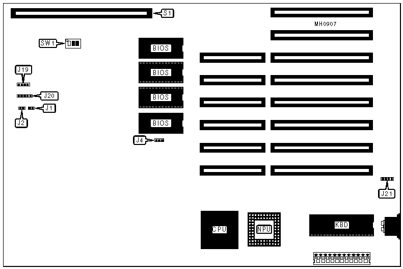
CONNECTIONS |
|||
|
Purpose |
Location |
Purpose |
Location |
|
Turbo LED |
J1 |
Power LED & keylock |
J20 |
|
Reset switch |
J2 |
External battery |
J21 |
|
Speaker |
J19 |
32-bit external memory card |
S1 |
|
USER CONFIGURABLE SETTINGS |
||||
|
Function |
Jumper/Switch |
Position |
||
|
» |
BIOS type select 27128 |
J4 |
pins 1 & 2 closed |
|
|
|
BIOS type select 27256 |
J4 |
pins 2 & 3 closed |
|
|
» |
Monitor type select color |
SW1/1 |
On |
|
|
|
Monitor type select monochrome |
SW1/1 |
Off |
|
|
» |
CPU speed select 8MHz |
SW1/2 |
On |
|
|
|
CPU speed select 16/20/25MHz |
SW1/2 |
Off |
|
|
» |
NPU disabled |
SW1/3 |
On |
|
|
|
NPU enabled |
SW1/3 |
Off |
|
|
|
Note : The cache is factory installed and can not be altered. The size and location of the cache and tag chips are unknown. |
|||
|
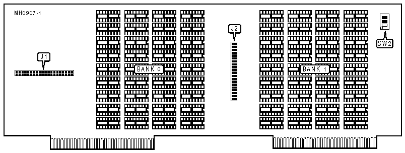
DRAM CONFIGURATION (CARD 1) |
||
|
Size |
Bank 0 |
Bank 1 |
|
1MB |
(36) 41256 |
None |
|
2MB |
(36) 41256 |
(36) 41256 |
|
DRAM SWITCH CONFIGURATION (CARD 1) |
||||
|
Size |
Base Memory |
SW2/1 |
SW2/2 |
SW2/3 |
|
512KB |
512KB |
Off |
Off |
Off |
|
640KB |
640KB |
Off |
On |
Off |
|
896KB |
512KB |
Off |
Off |
On |
|
1024KB |
640KB |
Off |
On |
On |
|
1536KB |
512KB |
On |
Off |
Off |
|
1664KB |
640KB |
On |
On |
Off |
|
1920KB |
512KB |
On |
Off |
On |
|
1920KB |
640KB |
On |
On |
On |
|
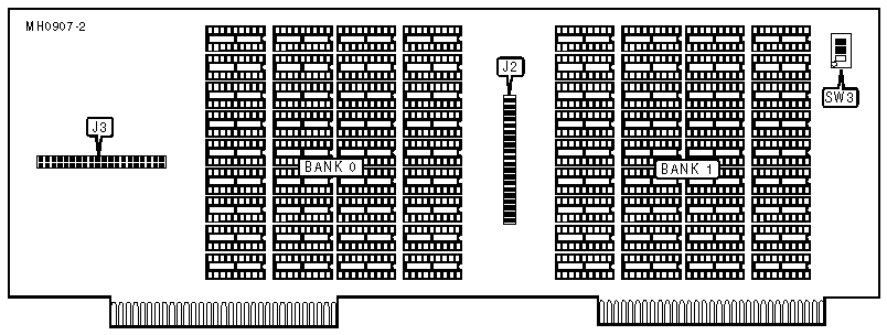
DRAM CONFIGURATION (CARD-2) |
||
|
Size |
Bank 0 |
Bank 1 |
|
4MB |
(36) 411000 |
None |
|
8MB |
(36) 411000 |
(36) 411000 |
|
DRAM SWITCH CONFIGURATION (CARD-2) |
||||
|
Size |
Base Memory |
SW3/1 |
SW3/2 |
SW3/3 |
|
3584KB |
512KB |
Off |
Off |
Off |
|
3712KB |
640KB |
Off |
On |
Off |
|
3968KB |
512KB |
Off |
Off |
On |
|
4096KB |
640KB |
Off |
On |
On |
|
7680KB |
512KB |
On |
Off |
Off |
|
7808KB |
640KB |
On |
On |
Off |
|
8064KB |
512KB |
On |
Off |
On |
|
8192KB |
640KB |
On |
On |
On |
|
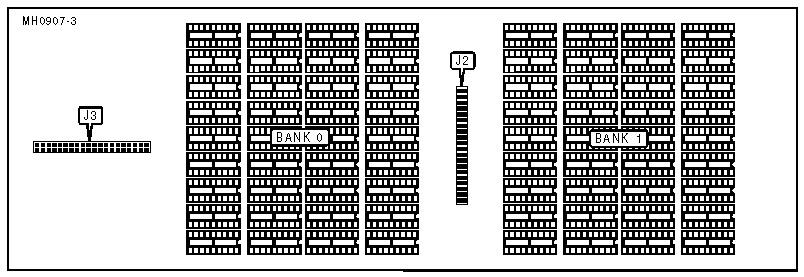
DAUGHTER BOARD DRAM CONFIGURATION |
||
|
Size |
Bank 0 |
Bank 1 |
|
4MB |
(36) 411000 |
None |
|
8MB |
(36) 411000 |
(36) 411000 |
|
Note: Each system memory card can be connected to a daughter board, for an additional 4 to 8MB of memory. The daughter board's Strips J2 & J3 (component side) plug into the J2 & J3 Strips (solder side) on the system memory boards. |
||
|
DAUGHTER BOARD DRAM SWITCH CONFIGURATION FOR CARD 1 |
|||
|
Size |
Base Memory |
SW2/1 |
SW2/2 |
|
5632KB |
512KB |
Off |
Off |
|
5760KB |
640KB |
Off |
On |
|
9728KB |
512KB |
On |
Off |
|
9856KB |
640KB |
On |
On |
|
Note: The system memory card must be filled to maximum capacity (2MB) to implement the daughter board. When the daughter board is plugged into the system memory board the switches previously used to set the base memory size on the system memory card is then used to set the base memory size of the daughter board. |
|||
|
DAUGHTER BOARD DRAM SWITCH CONFIGURATION FOR CARD 2 |
||||
|
Size |
Base Memory |
SW3/1 |
SW3/2 |
SW3/3 |
|
11776KB |
512KB |
Off |
Off |
N/A |
|
11904KB |
640KB |
Off |
On |
N/A |
|
14848KB |
512KB |
On |
Off |
On |
|
14976KB |
640KB |
On |
On |
On |
|
15744KB |
512KB |
On |
Off |
Off |
|
15872KB |
640KB |
On |
On |
Off |
|
Note: The system memory card must be filled to maximum capacity (8MB) to implement the daughter board. When the daughter board is plugged into the system memory board, the switches previously used to set the base memory size on the system memory card are then used to set the base memory size of the daughter board. |
||||