AMPRO COMPUTERS, INC.
LITTLE BOARD/P5E
|
Device Type |
Single board computer |
|
Processor |
Pentium |
|
Processor Speed |
100/133/166MHz |
|
Chip Set |
Unidentified |
|
Video Chip Set |
Chips and Technology |
|
Maximum Onboard Memory |
128MB |
|
Maximum Video Memory |
2MB |
|
Cache |
256KB |
|
BIOS |
Ampro |
|
Dimensions |
203mm x 146mm |
|
I/O Options |
Ethernet 10BaseT connector, AUI connector, floppy drive interface, IDE interface, SCSI interface, parallel port, serial ports (2), VGA interface, PC/104 connectors (2) |
|
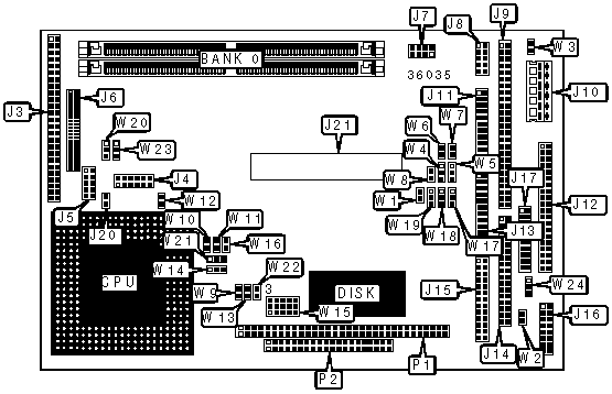
CONNECTIONS |
|||
|
Purpose |
Location |
Purpose |
Location |
|
Flat panel connector |
J3 |
Serial port 3 & 4 |
J13 |
|
VEE bias supply connector |
J4 |
Floppy drive interface |
J14 |
|
VGA interface |
J5 |
Parallel port |
J15 |
|
Video external overlay connector |
J6 |
Keyboard connector |
J16 |
|
Ethernet 10BaseT connector |
J7 |
IDE extension connector |
J17 |
|
AUI connector |
J8 |
CPU fan power |
J20 |
|
SCSI interface |
J9 |
PCI bus connector |
J21 |
|
Power connector |
J10 |
PC/104 connector |
P1 |
|
Serial port 1 & 2 |
J11 |
PC/104 connector |
P2 |
|
IDE interface |
J12 |
|
|
|
USER CONFIGURABLE SETTINGS |
|||
|
Function |
Label |
Position |
|
|
|
Vee polarity select negative |
W1 |
Pins 1 & 2 closed |
|
|
Vee polarity select positive |
W1 |
Pins 2 & 3 closed |
|
|
SCSI termination enabled |
W3 |
Closed |
|
|
SCSI termination disabled |
W3 |
Open |
|
|
+5v for external serial port 4 enabled |
W8 |
Closed |
|
|
+5v for external serial port 4 disabled |
W8 |
Open |
|
|
BIOS chip select swap enabled |
W9 |
Closed |
|
|
Byte wide chip select swap enabled |
W9 |
Open |
|
» |
Factory configured - do not alter |
W12 |
Open |
|
|
BIOS 12v programming power enabled |
W13 |
Closed |
|
|
BIOS 12v programming power disabled |
W13 |
Open |
|
» |
Factory configured - do not alter |
W16 |
Open |
|
|
SCSI interface enabled |
W17 |
Open |
|
|
SCSI interface disabled |
W17 |
Closed |
|
|
Backlight enable signal select optional |
W20 |
Pins 1 & 2 closed |
|
|
Backlight enable signal select standard |
W20 |
Pins 2 & 3 closed |
|
|
Byte wide write enabled |
W22 |
Closed |
|
|
Byte wide write disabled |
W22 |
Open |
|
» |
Data valid select high to low |
W23 |
Pins 1 & 2 closed |
|
|
Data valid select low to high |
W23 |
Pins 2 & 3 closed |
|
SIMM CONFIGURATION |
|
|
Size |
Bank 0 |
|
8MB |
(2) 1M x 36 |
|
16MB |
(2) 2M x 36 |
|
32MB |
(2) 4M x 36 |
|
64MB |
(2) 8M x 36 |
|
128MB |
(2) 16M x 36 |
|
CACHE CONFIGURATION |
|
Note: The location of the cache is unidentified. |
|
VIDEO MEMORY CONFIGURATION |
|
Note: The location of the video memory is unidentified. |
|
CPU SPEED SELECTION |
|||||
|
CPU speed |
Clock speed |
Multiplier |
W10 |
W11 |
W14 |
|
100MHz |
66MHz |
1.5x |
Closed |
Closed |
2 & 3 |
|
133MHz |
66MHz |
2x |
Open |
Closed |
2 & 3 |
|
166MHz |
66MHz |
2.5x |
Open |
Open |
2 & 3 |
|
Note: Pins designated should be in the closed position. |
|||||
|
DMA CHANNEL SELECTION |
||
|
Channel |
W18 |
W19 |
|
1 |
Pins 1 & 2 closed |
Pins 1 & 2 closed |
|
3 |
Pins 2 & 3 closed |
Pins 2 & 3 closed |
|
SERIAL PORT 3 ADDRESS SELECTION |
||
|
Setting |
W4 |
W6 |
|
IRQ4, shared with serial 1 |
Pins 1 & 2 closed |
Open |
|
Serial 3, IRQ12/serial 1 IRQ4 |
Pins 2 & 3 closed |
Closed |
|
SERIAL PORT 4 ADDRESS SELECTION |
||
|
Setting |
W5 |
W7 |
|
IRQ3, shared with serial 2 |
Pins 1 & 2 closed |
Open |
|
Serial 4, IRQ10/serial 2 IRQ3 |
Pins 2 & 3 closed |
Closed |
|
WATCHDOG TIMER SELECTION |
|
|
Setting |
W24 |
|
IOCHK |
Pins 1 & 2 closed |
|
Reset |
Pins 2 & 3 closed |
|
Disabled |
Open |
|
EPROM SELECTION |
|||
|
Type |
W2 |
W15 |
W21 |
|
27C64 |
Open |
8 & 9, 14 & 15 |
2 & 3 |
|
27C128 |
Open |
8 & 9, 14 & 15 |
2 & 3 |
|
28C64 |
Open |
8 & 9, 14 & 15 |
2 & 3 |
|
27C256 |
Open |
9 & 12, 14 & 15 |
1 & 2 |
|
27C512 |
Open |
9 & 12, 10 & 11, 14 & 15 |
1 & 2 |
|
27C010 |
Open |
2 & 5, 7 & 8, 9 & 12, 10 & 11 |
1 & 2 |
|
27C020 |
Open |
2 & 5, 7 & 8, 9 & 12, 10 & 11, 13 & 14 |
1 & 2 |
|
27C040 |
Open |
2 & 5, 4 & 7, 9 & 12, 10 & 11, 13 & 14 |
1 & 2 |
|
27C080 |
Open |
4 & 7, 5 & 6, 9 & 12, 10 & 11, 13 & 14 |
1 & 2 |
|
Note: Pins designated should be in the closed position. |
|||
|
FLASH EPROM SELECTION |
|||
|
Type |
W2 |
W15 |
W21 |
|
29C256 |
Open |
8 & 11, 9 & 12, 14 & 15 |
1 & 2 |
|
28C256 |
Open |
8 & 9, 11 & 12, 14 & 15 |
1 & 2 |
|
29F512 |
Open |
4 & 5, 7 & 8, 9 & 12, 10 & 11, 13 & 14 |
1 & 2 |
|
29F010 |
Open |
4 & 5, 7 & 8, 9 & 12, 10 & 11, 13 & 14 |
1 & 2 |
|
29F020 |
Open |
4 & 5, 7 & 8, 9 & 12, 10 & 11, 13 & 14 |
1 & 2 |
|
29F040 |
Open |
4 & 5, 7 & 8, 9 & 12, 10 & 11, 13 & 14 |
1 & 2 |
|
28F256 |
Open |
2 & 5, 7 & 8, 9 & 12, 10 & 11, 13 & 14 |
1 & 2 |
|
28F512 |
Open |
2 & 5, 7 & 8, 9 & 12, 10 & 11, 13 & 14 |
1 & 2 |
|
28F010 |
Open |
2 & 5, 7 & 8, 9 & 12, 10 & 11, 13 & 14 |
1 & 2 |
|
28F020 |
Open |
2 & 5, 7 & 8, 9 & 12, 10 & 11, 13 & 14 |
1 & 2 |
|
Note: Pins designated should be in the closed position. |
|||
|
SRAM SELECTION |
|||
|
Type |
W2 |
W15 |
W21 |
|
43256 |
Closed |
7 & 10, 8 & 9, 11 & 12, 14 & 15 |
2 & 3 |
|
628128 |
Closed |
7 & 10, 8 & 9, 11 & 12, 14 & 15 |
2 & 3 |
|
DS1235Y |
Closed |
7 & 10, 8 & 9, 11 & 12, 14 & 15 |
2 & 3 |
|
BQ4013Y |
Closed |
7 & 10, 8 & 9, 11 & 12, 14 & 15 |
2 & 3 |
|
628512 |
Closed |
4 & 5, 7 & 10, 8 & 9, 11 & 12, 13 & 14 |
2 & 3 |
|
DS1650Y |
Closed |
4 & 5, 7 & 10, 8 & 9, 11 & 12, 13 & 14 |
2 & 3 |
|
BQ4015Y |
Closed |
4 & 5, 7 & 10, 8 & 9, 11 & 12, 13 & 14 |
2 & 3 |
|
Note: Pins designated should be in the closed position. |
|||