EPSON, INC.
EQUITY 486DX2/50 PLUS
|
Processor |
80486DX2 |
|
Processor Speed |
50(internal)Mhz |
|
Chip Set |
Epson |
|
Max. Onboard DRAM |
16MB |
|
Cache |
32KB |
|
BIOS |
Epson |
|
Dimensions |
355mm x 304mm |
|
I/O Options |
32-bit external memory card slot, floppy drive interface, IDE interface, parallel port, PS/2 mouse port, serial port, VGA port |
|
NPU Options |
None |
|
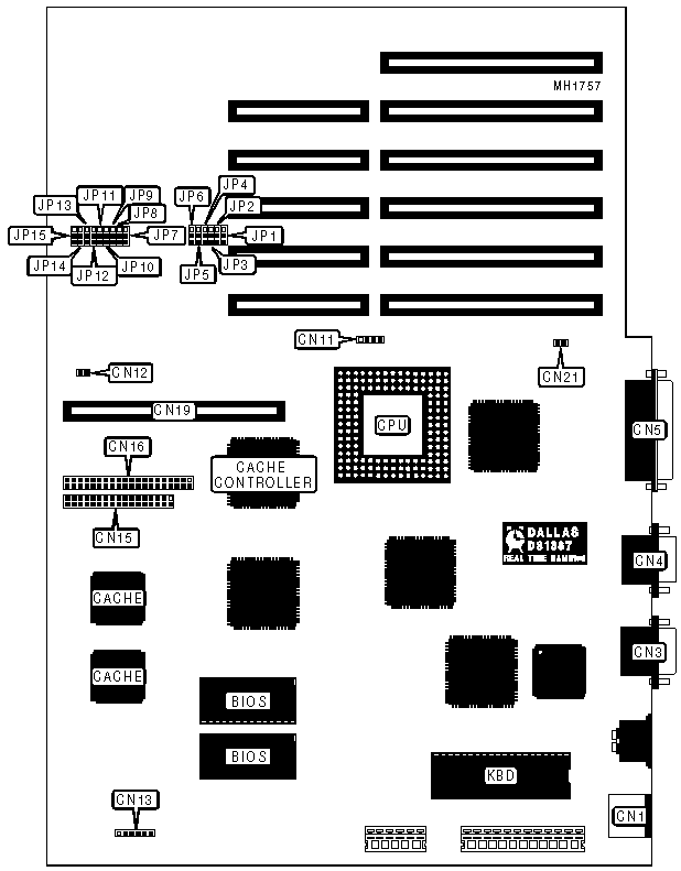
CONNECTIONS | |||
|
Purpose |
Location |
Purpose |
Location |
|
PS/2 mouse port |
CN1 |
Case connector block |
CN13 |
|
VGA port |
CN3 |
Floppy drive interface |
CN15 |
|
Serial port |
CN4 |
IDE interface LED |
CN16 |
|
Parallel port |
CN5 |
32-bit external memory card slot |
CN19 |
|
Hard drive LED |
CN11 |
Chassis fan power |
CN21 |
|
Speaker |
CN12 | ||
|
USER CONFIGURABLE SETTINGS | |||
|
Function |
Jumper |
Position | |
|
» |
Fatory configured - do not alter |
JP1 |
pins 2 & 3 closed |
|
» |
Fatory configured - do not alter |
JP2 |
pins 2 & 3 closed |
|
» |
Fatory configured - do not alter |
JP3 |
pins 2 & 3 closed |
|
» |
On-board VGA adapter enabled |
JP4 |
pins 1 & 2 closed |
|
On-board VGA adapter disabled |
JP4 |
pins 2 & 3 closed | |
|
» |
Password enabled |
JP5 |
pins 1 & 2 closed |
|
Password disabled |
JP5 |
pins 2 & 3 closed | |
|
» |
Monitor type select color |
JP6 |
pins 1 & 2 closed |
|
Monitor type select monochrome |
JP6 |
pins 2 & 3 closed | |
|
» |
Mouse port enabled |
JP7 |
pins 1 & 2 closed |
|
Mouse port disabled |
JP7 |
pins 2 & 3 closed | |
|
» |
Normal IOCHRDY signal enabled |
JP15 |
pins 2 & 3 closed |
|
Early IOCHRDY signal enabled |
JP15 |
pins 1 & 2 closed | |
|
DRAM CONFIGURATION | |||||||||
|
Size |
Bank 0 |
Bank 1 |
Bank 2 |
Bank 3 |
JP8 |
JP9 |
JP10 |
JP11 |
JP12 |
|
4MB |
(4) 4M x 9 |
NONE |
NONE |
NONE |
2 & 3 |
2 & 3 |
2 & 3 |
2 & 3 |
1 & 2 |
|
8MB |
(4) 4M x 9 |
(4) 4M x 9 |
NONE |
NONE |
2 & 3 |
2 & 3 |
2 & 3 |
1 & 2 |
1 & 2 |
|
9MB |
(4) 4M x 9 |
(4) 4M x 9 |
(4) 1M x 9 |
NONE |
1 & 2 |
2 & 3 |
2 & 3 |
1 & 2 |
1 & 2 |
|
10MB |
(4) 4M x 9 |
(4) 4M x 9 |
(4) 1M x 9 |
(4) 1M x 9 |
1 & 2 |
1 & 2 |
2 & 3 |
1 & 2 |
1 & 2 |
|
12MB |
(4) 4M x 9 |
(4) 4M x 9 |
(4) 4M x 9 |
NONE |
1 & 2 |
2 & 3 |
1 & 2 |
1 & 2 |
1 & 2 |
|
16MB |
(4) 4M x 9 |
(4) 4M x 9 |
(4) 4M x 9 |
(4) 4M x 9 |
1 & 2 |
1 & 2 |
1 & 2 |
1 & 2 |
1 & 2 |
|
Note:Pins designated should be in the closed position. Banks 0 - 3 are located on the external memory card. | |||||||||
|
BASE MEMORY CONFIGURATION | ||
|
Size |
JP13 |
JP14 |
|
256KB |
pins 2 & 3 closed |
pins 2 & 3 closed |
|
512KB |
pins 2 & 3 closed |
pins 1 & 2 closed |
|
640KB |
pins 1 & 2 closed |
pins 1 & 2 closed |