INFORMTECH INTERNATIONAL, INC.
INTEL PCI
|
Processor |
80486SX/80487SX/80486DX/Pentium Overdrive |
|
Processor Speed |
25/33MHz |
|
Chip Set |
Intel |
|
Max. Onboard DRAM |
64MB |
|
Cache |
64/128/256/512KB |
|
BIOS |
AMI |
|
Dimensions |
330mm x 218mm |
|
I/O Options |
32-bit PCI bus slots (3) |
|
NPU Options |
None |
|
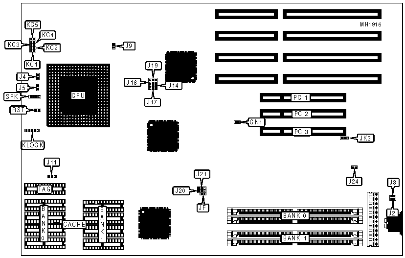
CONNECTIONS |
|||
|
Purpose |
Location |
Purpose |
Location |
|
SCSI bus LED |
CN1 |
32-bit PCI bus slot |
PCI2 |
|
Turbo switch |
J4 |
32-bit PCI bus slot |
PCI3 |
|
Turbo LED |
J5 |
Speaker |
SPK |
|
Power LED & keylock |
KLOCK |
Reset switch |
RST |
|
32-bit PCI bus slot |
PCI1 |
|
|
|
USER CONFIGURABLE SETTINGS |
|||
|
Function |
Jumper |
Position |
|
|
» |
CMOS memory normal operation |
CMOS |
Closed |
|
|
CMOS memory clear |
CMOS |
Open |
|
» |
Factory configured - do not alter |
J9 |
Closed |
|
» |
External cache installed |
J17 |
pins 2 & 3 closed |
|
|
External cache not installed |
J17 |
pins 1 & 2 closed |
|
» |
SCSI terminator power source from the system |
J24 |
Closed |
|
|
SCSI terminator power source from peripheral device |
J24 |
Open |
|
» |
Flash EPROM 27C020 or 27C010 installed |
JK3 |
pins 1 & 2 closed |
|
|
Flash EPROM 27C512 installed |
JK3 |
pins 2 & 3 closed |
|
Note:The location of CMOS jumper is unidentified. |
|||
|
DRAM CONFIGURATION |
||
|
Size |
Bank 0 |
Bank 1 |
|
2MB |
(2) 256K x 36 |
NONE |
|
4MB |
(2) 256K x 36 |
(2) 256K x 36 |
|
4MB |
(2) 512K x 36 |
NONE |
|
6MB |
(2) 256K x 36 |
(2) 512K x 36 |
|
6MB |
(2) 512K x 36 |
(2) 256K x 36 |
|
8MB |
(2) 512K x 36 |
(2) 512K x 36 |
|
8MB |
(2) 1M x 36 |
NONE |
|
10MB |
(2) 256K x 36 |
(2) 1M x 36 |
|
10MB |
(2) 1M x 36 |
(2) 256K x 36 |
|
12MB |
(2) 512K x 36 |
(2) 1M x 36 |
|
12MB |
(2) 1M x 36 |
(2) 512K x 36 |
|
16MB |
(2) 1M x 36 |
(2) 1M x 36 |
|
16MB |
(2) 2M x 36 |
NONE |
|
18MB |
(2) 256K x 36 |
(2) 2M x 36 |
|
18MB |
(2) 2M x 36 |
(2) 256K x 36 |
|
20MB |
(2) 512K x 36 |
(2) 2M x 36 |
|
20MB |
(2) 2M x 36 |
(2) 512K x 36 |
|
24MB |
(2) 1M x 36 |
(2) 2M x 36 |
|
24MB |
(2) 2M x 36 |
(2) 1M x 36 |
|
32MB |
(2) 2M x 36 |
(2) 2M x 36 |
|
32MB |
(2) 4M x 36 |
NONE |
|
34MB |
(2) 256K x 36 |
(2) 4M x 36 |
|
34MB |
(2) 4M x 36 |
(2) 256K x 36 |
|
36MB |
(2) 512K x 36 |
(2) 4M x 36 |
|
36MB |
(2) 4M x 36 |
(2) 512K x 36 |
|
40MB |
(2) 1M x 36 |
(2) 4M x 36 |
|
40MB |
(2) 4M x 36 |
(2) 1M x 36 |
|
48MB |
(2) 2M x 36 |
(2) 4M x 36 |
|
48MB |
(2) 4M x 36 |
(2) 2M x 36 |
|
64MB |
(2) 4M x 36 |
(2) 4M x 36 |
|
CACHE CONFIGURATION |
|||
|
Size |
Bank 0 |
Bank 1 |
TAG |
|
64KB |
(4) 8K x 8 |
(4) 8K x 8 |
(1) 8K x 8 |
|
128KB |
(4) 32K x 8 |
None |
(1) 8K x 8 |
|
256KB |
(4) 32K x 8 |
(4) 32K x 8 |
(1) 32K x 8 |
|
512KB |
(4) 128K x 8 |
None |
(1) 32K x 8 |
|
CACHE JUMPER CONFIGURATION |
||||||
|
Size |
J6 |
J7 |
J8 |
J11 |
J18 |
J19 |
|
64KB |
Open |
Open |
Open |
pins 2 & 3 closed |
pins 1 & 2 closed |
pins 1 & 2 closed |
|
128KB |
Closed |
Open |
Open |
pins 1 & 2 closed |
pins 2 & 3 closed |
pins 1 & 2 closed |
|
256KB |
Closed |
Closed |
Open |
pins 1 & 2 closed |
pins 1 & 2 closed |
pins 2 & 3 closed |
|
512KB |
Closed |
Closed |
Closed |
pins 1 & 2 closed |
pins 2 & 3 closed |
pins 2 & 3 closed |
|
. CPU TYPE CONFIGURATION (CONT.) |
|||
|
Type |
J106 |
J107 |
J109 |
|
SL-enhanced CPU |
Closed |
Closed |
pins 2 & 3 closed |
|
Normal CPU |
N/A |
N/A |
pins 1 & 2 closed |
|
. CPU TYPE CONFIGURATION (CONT.) |
||||||||
|
Type |
KC1 |
KC2 |
KC3 |
KC4 |
KC5 |
JF |
J20 |
J21 |
|
80486SX |
Open |
Open |
Open |
Closed |
Open |
Closed |
2 & 3 |
1 & 2 |
|
80487SX |
Open |
Closed |
Closed |
Open |
Closed |
Closed |
2 & 3 |
1 & 2 |
|
80486DX |
Closed |
Open |
Closed |
Open |
Closed |
Closed |
2 & 3 |
1 & 2 |
|
Pentium Overdrive |
Open |
Closed |
Closed |
Open |
Closed |
Open |
2 & 3 |
1 & 2 |
|
Note:Pins designated should be in the closed position. |
||||||||
|
CPU SPEED CONFIGURATION |
|||
|
Speed |
JP3 |
J12 |
J13 |
|
25MHz |
Closed |
pins 1 & 2 closed |
pins 2 & 3 closed |
|
33MHz |
Closed |
pins 1 & 2 closed |
pins 1 & 2 closed |
|
VESA WAIT STATE/BUS SPEED CONFIGURATION |
||
|
Speed |
Wait states |
J14 |
|
£ 33MHz |
0 wait states |
pins 2 & 3 closed |
|
> 33MHz |
1 wait state |
pins 1 & 2 closed |
|
PCI SLAVE/MASTERSLAVE CONFIGURATION |
|||||
|
Slot |
Type |
J102 |
J103 |
J104 |
J105 |
|
1 |
Slave |
N/A |
N/A |
Pins 1 & 2 |
Pins 1 & 2 |
|
1 |
Master |
N/A |
N/A |
Pins 2 & 3 |
Pins 2 & 3 |
|
2 |
Slave |
N/A |
N/A |
Pins 2 & 3 |
Pins 2 & 3 |
|
2 |
Master |
N/A |
N/A |
Pins 1 & 2 |
Pins 1 & 2 |
|
3 |
Slave |
Pins 2 & 3 |
Pins 2 & 3 |
N/A |
N/A |
|
3 |
Master |
Pins 1 & 2 |
Pins 1 & 2 |
N/A |
N/A |
|
SCSI |
Slave |
Pins 1 & 2 |
Pins 1 & 2 |
N/A |
N/A |
|
SCSI |
Master |
Pins 2 & 3 |
Pins 2 & 3 |
N/A |
N/A |
|
Note:Pins designated should be in the closed position. |
|||||
|
PCI IRQ INTERRUPT SELECT |
||||||
|
PCI1 |
J37 |
J36 |
J39 |
J40 |
J42 |
J43 |
|
PCI-1-INTA |
pins 1 & 2 |
pins 1 & 2 |
pins 1 & 2 |
pins 1 & 2 |
pins 1 & 2 |
pins 1 & 2 |
|
PCI-2-INTA |
pins 2 & 3 |
pins 1 & 2 |
pins 2 & 3 |
pins 2 & 3 |
pins 2 & 3 |
pins 2 & 3 |
|
PCI-2-INTA |
pins 2 & 3 |
pins 1 & 2 |
pins 2 & 4 |
pins 2 & 4 |
pins 2 & 4 |
pins 2 & 4 |
|
Note:Pins designated should be in the closed position. For every INTA signal, only one of IRQ5-IRQ15 should be connected. |
||||||
|
ON BOARD SCSI CONFIGURATION |
||
|
SCSI |
J2 |
J3 |
|
Enabled |
Closed |
Closed |
|
Disabled |
Open |
Open |
|
Note:When the on board SCSI is disconnected from the power, the power cost should go down. |
||