NETWORK INTERFACE TECHNOLOGY CORPORATION
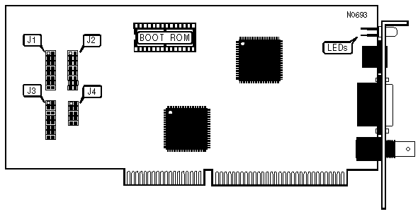
ETHERPRO II
|
NIC Type |
Ethernet |
|
Transfer Rate |
10Mbps |
|
Data Bus |
16-bit ISA |
|
Topology |
Linear Bus, Star |
|
Wiring Type |
Unshielded twisted pair RG58A/U 50ohm coaxial AUI transceiver via DB-15 port |
|
Boot ROM |
Available |
|
BASE I/O ADDRESS SELECT | ||
|
Address Range |
J1 | |
| » |
Software configured |
Pins 1 & 2 closed |
|
360h |
Pins 3 & 4 closed | |
|
340h |
Pins 5 & 6 closed | |
|
320h |
Pins 7 & 8 closed | |
|
300h |
Pins 9 & 10 closed | |
|
2A0h |
Pins 11 & 12 closed | |
|
280h |
Pins 13 & 14 closed | |
|
240h |
Pins 15 & 16 closed | |
|
220h |
Pins 17 & 18 closed | |
|
Note: These settings apply when the LAN card is not in ELNK/16BIT compatibility mode. | ||
|
BASE I/O ADDRESS SELECT | ||
|
Address Range |
J1 | |
| » |
Software configured |
Pins 1 & 2 closed |
|
350h |
Pins 3 & 4 closed | |
|
330h |
Pins 5 & 6 closed | |
|
310h |
Pins 7 & 8 closed | |
|
300h |
Pins 9 & 10 closed | |
|
2E0h |
Pins 11 & 12 closed | |
|
2A0h |
Pins 13 & 14 closed | |
|
280h |
Pins 15 & 16 closed | |
|
250h |
Pins 17 & 18 closed | |
|
Note: These settings apply when the LAN card is in ELNK/16BIT compatibility mode. | ||
|
BASE MEMORY ADDRESS CONFIGURATION | ||
|
Address Range |
J3 | |
| » |
Software configured |
Pins 1 & 2 closed |
|
Disabled |
Pins 3 & 4 closed | |
|
DC000h |
Pins 5 & 6 closed | |
|
D8000h |
Pins 7 & 8 closed | |
|
D4000h |
Pins 9 & 10 closed | |
|
D0000h |
Pins 11 & 12 closed | |
|
CC000h |
Pins 13 & 14 closed | |
|
C8000h |
Pins 15 & 16 closed | |
|
Note: These settings apply when the LAN card is not in ELNK/16BIT compatibility mode. | ||
|
BASE MEMORY ADDRESS SELECT | ||
|
Address Range |
J3 | |
| » |
Software configured |
Pins 1 & 2 closed |
|
Disabled |
Pins 3 & 4 closed | |
|
DC000h |
Pins 5 & 6 closed | |
|
D8000h |
Pins 7 & 8 closed | |
|
CC000h |
Pins 9 & 10 closed | |
|
C8000h |
Pins 11 & 12 closed | |
|
Note: These settings apply when the LAN card is in ELNK/16BIT compatibility mode. | ||
|
COMPATIBILITY MODE | ||
|
Mode |
J4 | |
| » |
Software configured |
Pins 1 & 2 closed |
|
N2000 (C & T) |
Pins 3 & 4 closed | |
|
N2000 (STD) |
Pins 5 & 6 closed | |
|
N1000 TURBO |
Pins 7 & 8 closed | |
|
03EBT/13EBT |
Pins 9 & 10 closed | |
|
ELNKII/16BIT |
Pins 11 & 12 closed | |
|
INTERRUPT SELECT | ||
|
IRQ |
J2 | |
| » |
Software configured |
Pins 1 & 2 closed |
|
IRQ15 |
Pins 3 & 4 closed | |
|
IRQ11 |
Pins 5 & 6 closed | |
|
IRQ10 |
Pins 7 & 8 closed | |
|
IRQ7 |
Pins 9 & 10 closed | |
|
IRQ5 |
Pins 11 & 12 closed | |
|
IRQ4 |
Pins 13 & 14 closed | |
|
IRQ3 |
Pins 15 & 16 closed | |
|
IR/FONT> |
Pins 17 & 18 closed | |

|
DIAGNOSTIC LED(S) | |||
|
LED |
Color |
Status |
Condition |
|
LED1 |
Green |
Off |
No link established |
|
LED1 |
Green |
On |
Link established |
|
LED1 |
Green |
Blinking |
Data is being received |
|
LED2 |
Red |
Off |
Polarity normal |
|
LED2 |
Red |
On |
Polarity reversed |
|
LED2 |
Red |
Blinking |
Data is being transmitted |