BANKSIA TECHNOLOGY PTY, LTD.
PRO 144
|
Card Type |
Fax, Modem (synchronous/asynchronous) |
|
Chip Set |
Unidentified |
|
Maximum Data Rate |
14.4Kbps |
|
Maximum Fax Rate |
14.4Kbps |
|
Data Bus |
External |
|
Fax Class |
Class I |
|
Data Modulation Protocol |
Bell 103/212A ITU-T V.21, V.22, V.22bis, V.23, V.32, V.32bis |
|
Fax Modulation Protocol |
ITU-T V.17, V.27ter, V.29 |
|
Error Correction/Compression |
MNP5, MNP10, V.42, V.42bis |
|
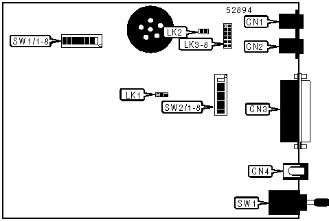
CONNECTIONS | ||||||
|
Function |
Label |
Function |
Label | |||
|
Auxiliary port |
CN1 |
DC power |
CN4 | |||
|
Line out |
CN2 |
Power switch |
SW1 | |||
|
RS-232/422 |
CN3 | |||||
|
USER CONFIGURABLE SETTINGS | ||
|
Setting |
Label |
Position |
|
í DTR signal ignored |
SW1/1 |
On |
|
DTR signal normal |
SW1/1 |
Off |
|
í DCD and DSR forced high |
SW1/2 |
On |
|
DCD and DSR normal |
SW1/2 |
Off |
|
í Echo disabled |
SW1/3 |
On |
|
Echo enabled |
SW1/3 |
Off |
|
í Result codes disabled |
SW1/4 |
On |
|
Result codes enabled |
SW1/4 |
Off |
|
í Leased-line operation |
SW1/5 |
On |
|
Switched line operation |
SW1/5 |
Off |
|
í Auto-answer enabled on 2nd ring |
SW1/6 |
On |
|
Auto-answer disabled on 2 nd ring |
SW1/6 |
Off |
|
í Synchronous mode 2 enabled |
SW1/7 |
On |
|
Synchronous mode 2 disabled |
SW1/7 |
Off |
|
í Dumb mode |
SW1/8 |
On |
|
Smart mode |
SW1/8 |
Off |
|
í Flow control to XON/XOFF enabled |
SW2/1 |
On |
|
Flow control to XON/XOFF disabled |
SW2/1 |
Off |
|
í V.25bis command set synchronous HDLC (NRZI) enabled |
SW2/2 |
On |
|
V.25bis command set synchronous HDLC (NRZI) disabled |
SW2/2 |
Off |
|
í Factory configured - DO NOT ALTER |
SW2/5 |
Unidentified |
|
í Factory configured - DO NOT ALTER |
SW2/6 |
Unidentified |
|
í Factory configured - DO NOT ALTER |
SW2/7 |
Unidentified |
|
í Factory defaults loaded up on power-up |
SW2/8 |
On |
|
Do no force factory defaults on power-up |
SW2/8 |
Off |
|
í Factory configured - DO NOT ALTER |
LK2 |
Unidentified |
|
AUXILIARY PORT | |||||||
|
Setting |
LK1 |
LK3 |
LK4 |
LK5 |
LK6 |
LK7 |
LK8 |
|
í PSTN |
Pins 2 & 3 closed |
Closed |
Closed |
Closed |
Open |
Closed |
Open |
|
Leased line |
Pins 1 & 2 closed |
Open |
Closed |
Open |
Closed |
Closed |
Closed |
|
MODULATION SELECTION | ||
|
Setting |
SW2/3 |
SW2/4 |
|
factory/stored setting |
Off |
Off |
|
14400 carrier |
Off |
On |
|
9600 carrier |
On |
Off |
|
2400 carrier |
On |
On |
|
SUPPORTED COMMAND SET |
|
Basic AT Commands |
|
AT, ‘Comma’ |
|
A, B, E, H, L, M, N, O, P, Q, S, T, V, W, X, Y, Z |
|
&C, &D, &G, &L, &R, &S, &V, &W, &X, &Y, &Z |
|
Extended AT Commands |
|
\B, \G, \J, \V, \Y, \Z |
|
Special Commands |
|
*H, )M |
|
S Registers |
|
S0, S1, S2, S3, S4, S5, S6, S7, S8, S9, S10, S11, S12, S14, S16, S18, S21, S22, S25, S26, S36 |
|
S37, S38 |
|
Note: See MHI Help file for full command documentation. |
Proprietary AT Command Set
|
ACKNOWLEDGMENT TIMER (T401) | |
|
Type: |
Configuration |
|
Format: |
AT [cmds] %Wn [cmds] |
|
Default: |
Unidentified |
|
Range: |
0-63 |
|
Unit: |
Unidentified |
|
Description: |
Wait to retransmit time out |
|
Note: |
T401 = 4 seconds + n x 100ms. Exception when in MNP mode: If n=0 use Microcom timers. If n=63 use ITU-T V42 Annex A timers. |
|
ANSWER LOGON SEQUENCE | |
|
Type: |
Register |
|
Format: |
AT [cmds] S34=n [cmds] |
|
Default: |
0 |
|
Range: |
0, 128-137 |
|
Unit: |
Unidentified |
|
Description: |
Controls answer logon sequence |
|
Note: |
If ATS34=0, then no logon in answer mode |
|
AUTO-RELIABLE FALLBACK CHARACTER | |
|
Type: |
Configuration |
|
Format: |
AT [cmds] S46=n [cmds] |
|
Default: |
13 |
|
Range: |
0-127 |
|
Unit: |
ASCII |
|
Description: |
Sets the character used as the auto-reliable fallback character; %A0 will disable this function. |
|
AUTO-RETRAIN | |
|
Type: |
Configuration |
|
Format: |
AT [cmds] &En [cmds] |
|
Description: |
Controls auto-retrain mode |
|
Command |
Function |
|
&E0 |
Auto-retrain disabled |
|
í &E1 |
Auto-retrain enabled |
|
BIT-MAPPED REGISTER S23 | ||
|
Format |
AT [cmds] S23=n [cmds] | |
|
Default: |
Unidentified | |
|
Range: |
0-189 | |
|
Unit: |
Bit-mapped | |
|
Description: |
Grants/denies remote digital loopback, controls DTE rate and parity, and sets guard tone. | |
|
Bit |
Value |
Function |
|
0 |
0 í 1 |
Remote digital loopback denied Remote digital loopback allowed |
|
3 - 1 |
000 001 010 011 100 101 110 111 |
Sets serial port speed to 0-300bps Sets serial port speed to 600bps Sets serial port speed to 1200bps Sets serial port speed to 2400bps Sets serial port speed to 4800bps Sets serial port speed to 9600bps Sets serial port speed to 19200bps Sets serial port speed to 38400bps |
|
5, 4 |
00 01 10 11 |
Parity even Space Parity Parity odd Mark or No Parity |
|
7, 6 |
00 01 10 |
Guard tone disabled Guard tone 550Hz enabled Guard tone 1800Hz enabled |
|
BIT-MAPPED REGISTER S24 | |||||
|
Format: |
AT [cmds] S24=n [cmds] | ||||
|
Default: |
143 | ||||
|
Range: |
0-255 | ||||
|
Description: |
Controls error control fallback character, error control buffer, data compression, auto-mode detection, extended result code, and lock serial port speed. | ||||
|
Bit |
Value |
Function | |||
|
0 |
0 í 1 |
No fallback character Enable fallback character in S46 | |||
|
1 |
0 í 1 |
Do not buffer data Buffer data | |||
|
2 |
0 í 1 |
Data compression disabled Data compression enabled | |||
|
4, 3 |
00 í 0110 |
S37 speed Optimum speed up to DTE if ATS37=255 Optimum speed if ATS37=255, except V.34 is disabled | |||
|
6, 5 |
í 0001 10 |
Extended result codes enabled Hayes extended result codes enabled Microcom extended result codes enabled | |||
|
7 |
0 í 1 |
Serial speed locked Serial speed follows connect speed | |||
|
BIT-MAPPED REGISTER S27 | ||
|
Format |
AT [cmds] S27=n [cmds] | |
|
Default: |
10 | |
|
Range: |
0-111 | |
|
Unit: |
Bit-mapped | |
|
Description: |
Selects synchronous/asynchronous mode, line type, clock source, and ITU-T/Bell modes. | |
|
Bit |
Value |
Function |
|
3, 1, 0 |
000 001 010 011 100 101 í 110111 |
Asynchronous direct mode enabled Synchronous mode 1 Synchronous mode 2 Synchronous mode 3 Direct mode Error correction mode V.42/MNP error correction mode V.42 error correction mode only |
|
2 |
í 01 |
Switched line Leased line |
|
5, 4 |
í 0001 10 |
Local modem generates transmit clock source Local DTE generates transmit clock source Remote DCE/DTE generates transmit clock source |
|
6 |
í 01 |
ITU/T mode Bell mode |
|
BIT-MAPPED REGISTER S28 | |||||
|
Format: |
AT [cmds] S28=n [cmds] | ||||
|
Default: |
8 | ||||
|
Range: |
0-255 | ||||
|
Description: |
Controls maximum block size, V.42 detection period (T4ØØ) in 5Ø milliseconds increments, and ODP/ADP | ||||
|
Bit |
Value |
Function | |||
|
1, 0 |
00 01 10 í 11 |
64 bytes 128 bytes 192 bytes 256 bytes | |||
|
6 - 2 |
00000 ….to…. í 10000….to…. 11111 |
Infinite time for detection ….to…. .8 seconds ….to…. 7.75 seconds | |||
|
7 |
0 í 1 |
Disable ODP/ADP when initiating a reliable V.42 handshake Enable ODP/ADP when initiating a reliable V.42 handshake | |||
|
BIT-MAPPED REGISTER S29 | |||||
|
Format: |
AT [cmds] S29=n [cmds] | ||||
|
Default: |
0 | ||||
|
Range: |
0-255 | ||||
|
Description: |
Controls V.42 acknowledgment timer (T4Ø1), V.42 frame check sequence, and V.42 selective reject | ||||
|
Bit |
Value |
Function | |||
|
5 - 0 |
í 000000000001 .…to…. 111111 |
4 seconds 4.1 ….to…. 10.3 seconds | |||
|
6 |
í 01 |
Always use CRC-16 Attempt use if CRC-32 | |||
|
7 |
í 01 |
Disable V.42 selective reject Enable V.42 selective reject | |||
|
BIT-MAPPED REGISTER S30 | |||||
|
Format: |
AT [cmds] S30=n [cmds] | ||||
|
Default: |
15 | ||||
|
Range: |
0-255 | ||||
|
Description: |
Controls V.42 windows size Negative ADP, asynchronous MNP2, and remote loopback test | ||||
|
Bit |
Value |
Function | |||
|
4 - 0 |
00000 00001 .…to…. í 01111.…to…. 11111 |
Not used 1 packet ….to…. 15 packets .…to…. 31 packets | |||
|
5 |
í 01 |
Disable negative ADP Enable negative ADP | |||
|
6 |
í 01 |
Do not force asynchronous MNP2 Force asynchronous MNP2 | |||
|
7 |
í 01 |
Ignore loopback frame received from remote Process loopback frame received from remote | |||
|
BIT-MAPPED REGISTER S31 | |||||
|
Format: |
AT [cmds] S31=n [cmds] | ||||
|
Default: |
0 | ||||
|
Range: |
0-159 | ||||
|
Description: |
Controls V.25 bis selection, synchronous mode V.13, abort, DTE Autobauding, and V.25 bis mode. | ||||
|
Bit |
Value |
Function | |||
|
1, 0 |
í 0001 10 11 |
Asynchronous V.25 Bisync V.25 bis NRZ HDLC V.25 bis NRZ HDLC V.25 bis NRZI | |||
|
2 |
í 01 |
Disable Synchronous mode V.13 Enable Synchronous mode V.13 | |||
|
3 |
í 01 |
Ignore keyboard abort on answer disabled Ignore keyboard abort on answer enabled | |||
|
4 |
í 01 |
Enable DTE Autobauding Disable DTE Autobauding | |||
|
6, 5 |
í 00 |
Not used | |||
|
7 |
í 01 |
AT commands enabled V.25bis enabled as per bits 1,Ø | |||
|
BIT-MAPPED REGISTER S32 | |||||
|
Format: |
AT [cmds] S32=n [cmds] | ||||
|
Default: |
0 | ||||
|
Range: |
0-255 | ||||
|
Description: |
Controls encryption mode, MNP extended services, power level adjustment, MNP10 - link negotiation, and MNP1Ø selection. | ||||
|
Bit |
Value |
Function | |||
|
1, 0 |
í 0001 10 11 |
No encryption Force V.42bis encryption Not used Not used | |||
|
3, 2 |
í 0001 10 |
MNP Extended Services disabled MNP Extended Services enabled MNP Extended Services enabled without MNP indication during the answer detect phase | |||
|
4 |
í 01 |
Power level adjustment disabled Power level adjustment enabled | |||
|
6, 5 |
í 0001 10 |
Link will be negotiated at highest possible speed Link will be negotiated at 1200bps Link will be negotiated at 4800bps | |||
|
7 |
í 01 |
MNP10 enabled MNP10 disabled | |||
|
BIT-MAPPED REGISTER S39 | |||||
|
Format: |
AT [cmds] S39=n [cmds] | ||||
|
Default: |
128 | ||||
|
Range: |
0-252 | ||||
|
Description: |
Controls, DTE rate at 230.4Kbps, DTE rate at 115.2Kbps, break handling, EIA loopback test, and auto retrain | ||||
|
Bit |
Value |
Function | |||
|
1, 0 |
í 00 |
Not used | |||
|
2 |
í 01 |
DTE rate is according to bits 1-3 of S23 or bit 3 of S39 DTE rate fixed at 23Ø4ØØ bps | |||
|
3 |
í 01 |
DTE rate is according to bits 1-3 of S23 or bit 2 of S39 DTE rate fixed at 1152ØØ bps | |||
|
5, 4 |
í 0010 11 |
Break sent in sequence with received data Break sent immediately to DTE Buffers cleared, break sent to DTE | |||
|
6 |
í 01 |
Disabled EIA loopback test Enabled EIA loopback test | |||
|
7 |
0 í 1 |
Auto retrain disabled Auto retrain enabled | |||
|
BIT-MAPPED REGISTER S49 | |||||
|
Format: |
AT [cmds] S49=n [cmds] | ||||
|
Default: |
Unidentified | ||||
|
Range: |
0-255 | ||||
|
Description: |
Controls flow control, compromise equalizer value, smart/dumb mode, and, compromise equalizer. | ||||
|
Bit |
Value |
Function | |||
|
4 - 0 |
00000 í 0001100100 01000 01100 10000 10100 |
Flow control disabled Hardware flow control DCE to DTE, bi-directional flow control DCE to DTE, unidirectional flow control DCE to DTE, bi-directional, transparent flow control DCE to remote modem, bi-directional flow control DTE to DCE to remote modem bi-directional flow control | |||
|
5 |
0 1 |
3 dB when compromise equalizer enabled 6 dB when compromise equalizer enabled | |||
|
6 |
í 01 |
Smart mode Dumb mode | |||
|
7 |
í 01 |
Compromise equalizer enabled Compromise equalizer disabled | |||
|
BREAK MODE | ||
|
Type: |
Configuration | |
|
Format: |
AT [cmds] &In [cmds] | |
|
Description: |
Controls how the modem handles break conditions on the DTE interface | |
|
Command |
Function | |
|
í &IØ |
Break sent in sequence with received data | |
|
&I1 |
Break sent immediately to DTE | |
|
&I2 |
Buffers cleared, break sent to DTE | |
|
BREAK TYPE | ||
|
Type: |
Configuration | |
|
Format: |
AT [cmds] \Kn [cmds] | |
|
Description: |
Configures action of break signal | |
|
Command |
Break from DTE | |
|
\K0 |
Online command mode enabled, send no break to remote modem | |
|
\K1 |
Break sent to remote modem and buffers cleared | |
|
\K2 |
Online command mode enabled, send no break to remote modem | |
|
\K3 |
Send break to remote modem immediately | |
|
\K4 |
Online command mode enabled, send no break to remote modem | |
|
í \K5 |
Send break with transmitted data | |
|
BUFFERED DATA ON HANG-UP | ||
|
Type: |
Configuration | |
|
Format: |
AT [cmds] %Dn [cmds] | |
|
Default: |
Unidentified | |
|
Range: |
0-255 | |
|
Unit: |
1 second | |
|
Description: |
Wait for receive buffer to be sent to DTE before hanging up | |
|
Command |
Function | |
|
%DØ |
Hang up without clearing buffer | |
|
COMMUNICATIONS MODE | |
|
Type: |
Configuration |
|
Format: |
AT [cmds] &Qn [cmds] |
|
Description: |
Selects communications mode options |
|
Command |
Mode |
|
&Q0 |
Asynchronous mode enabled |
|
&Q1 |
Synchronous mode 1 enabled |
|
&Q2 |
Synchronous mode 2 enabled |
|
&Q3 |
Synchronous mode 3 enabled |
|
&Q4 |
Asynchronous direct mode |
|
&Q5 |
MNP Error correction mode |
|
í &Q6 |
V.42/MNP error correction mode |
|
&Q7 |
V.42 error correction mode only |
|
CONNECT MODE | |
|
Type: |
Configuration |
|
Format: |
AT [cmds] \Nn [cmds] |
|
Description: |
Controls the type of connection the modem will operate in |
|
Command |
Function |
|
\N0 |
Normal mode enabled |
|
\N1 |
Direct mode enabled |
|
\N2 |
MNP reliable mode enabled |
|
\N3 |
Auto-reliable mode enabled |
|
\N4 |
V.42 reliable mode enabled |
|
\N5 |
MNP auto-reliable mode enabled |
|
\N6 |
Reliable mode enabled |
|
í \N7 |
Auto-reliable mode enabled |
|
DIAL | |
|
Type: |
Immediate |
|
Format: |
AT [cmds] D<#> [cmds] |
|
Description: |
Dials telephone number according to any modifiers included in the string |
|
Note: |
Any combination of modifiers can be used to produce the desired dial functions in sequence. |
|
Modifier |
Function |
|
J |
Link will be negotiated at 1200bps, AT*H1 command |
|
K |
Power level adjustment enabled, AT)M1 command |
|
P |
Pulse dialing enabled |
|
S=n |
Dial stored telephone number n |
|
T |
Tone dialing enabled/Pulse dialing disabled |
|
, |
Dialing paused for amount of time specified in S8 register |
|
DIAL ATTEMPTS | |
|
Type: |
Register |
|
Format: |
AT [cmds] S41=n [cmds] |
|
Default: |
0 |
|
Range: |
0-10 |
|
Unit: |
1 attempt |
|
Description: |
Controls the number of time the modem will redial |
|
DTE AUTOBAUDING | ||
|
Type: |
Configuration | |
|
Format: |
AT [cmds] %Bn [cmds] | |
|
Description: |
When AT%B1 is set, the modem will only respond to commands at the same port (DTE) speed | |
|
Note: |
This command can be used to lock the port speed, see AT\J in the MHI Help file. | |
|
Command |
Function | |
|
%B0 |
DTE autobauding enabled | |
|
í %B1 |
DTE autobauding disabled | |
|
DTE SPEED - DATA MODE | ||
|
Type: |
Configuration | |
|
Format: |
AT [cmds] &Bn [cmds] | |
|
Description: |
Controls DTE speed during data mode | |
|
Command |
Function | |
|
&B0 |
DTE speed follows connect speed | |
|
í &B1 |
DTE speed equals last AT command speed or the default value on power up | |
|
ERROR CONTROL BUFFER | ||
|
Type: |
Configuration | |
|
Format: |
AT [cmds] &On [cmds] | |
|
Description: |
Controls how buffering is performed during the error control negotiation period | |
|
Note: |
This command affects how data received is processed by the DCE | |
|
Command |
Function | |
|
&O0 |
Discard data received during negotiation | |
|
í &O1 |
Buffer data received during negotiation. Data will be sent to the DTE after the connect result code, if error control negotiation fails. | |
|
ERROR CORRECTION | ||
|
Type: |
Read-only | |
|
Format: |
AT [cmds] S44? [cmds] | |
|
Description: |
Displays which error correction method is in use | |
|
Value |
Meaning | |
|
0 |
Error correction disabled | |
|
2 |
MNP class 2 enabled | |
|
3 |
MNP class 3 enabled | |
|
4 |
MNP class 4 enabled | |
|
5 |
MNP class 5 enabled | |
|
6 |
V.42 enabled | |
|
7 |
V.42bis enabled | |
|
FACTORY DEFAULT PROFILE | ||
|
Type: |
Configuration | |
|
Format: |
AT [cmds] &F [cmds] | |
|
Description: |
Sets values in active profile to values found in the default profile | |
|
Command |
Function | |
|
&FØ |
V.42 factory defaults | |
|
&F1 |
MNP factory defaults | |
|
&F2 |
Basic asynchronous operation defaults | |
|
FLASH MEMORY DOWNLOAD | |
|
Type: |
Immediate |
|
Format: |
AT [cmds] %FLOAD [cmds] |
|
Description: |
Retrieve upgrade code to modem through serial port |
|
FLOW CONTROL | |
|
Type: |
Configuration |
|
Format: |
AT [cmds] &Kn [cmds] |
|
Description: |
Enables flow control options |
|
Command |
Function |
|
&K0 |
Flow control disabled |
|
í &K3 |
Local RTS/CTS flow control enabled |
|
&K4 |
Local XON/XOFF flow control enabled |
|
&K8 |
Unidirectional Software flow control enabled |
|
&K12 |
Software flow control - XON/XOFF enabled |
|
&K16 |
Software - Internal XON/XOFF flow control enabled |
|
&K20 |
Software - Local XON/XOFF flow control enabled |
|
FLOW CONTROL CHARACTER - XOFF | |
|
Type: |
Register |
|
Format: |
AT [cmds] S48=n [cmds] |
|
Default: |
19 |
|
Range: |
0-255 |
|
Unit: |
ASCII |
|
Description: |
Sets the character used to represent XOFF |
|
FLOW CONTROL CHARACTER - XON | |
|
Type: |
Register |
|
Format: |
AT [cmds] S47=n [cmds] |
|
Default: |
17 |
|
Range: |
0-255 |
|
Unit: |
ASCII |
|
Description: |
Sets the character used to represent XON |
|
INACTIVITY TIMER | |
|
Type: |
Register |
|
Format: |
AT [cmds] S40=n [cmds] |
|
Default: |
0 |
|
Range: |
0-255 |
|
Unit: |
1 minute |
|
Description: |
Sets the length of time that the modem does not receive information before it disconnects; S90=0 will disable. |
|
INGORE KEYBOARD ABORT DURING ANSWER MODE | |
|
Type: |
Configuration |
|
Format: |
AT [cmds] %Qn [cmds] |
|
Description: |
Controls the modem to ignore any data sent to the modem while it is in answer mode |
|
Command |
Function |
|
í %Q0 |
Keyboard abort disabled |
|
%Q1 |
Keyboard abort enabled |
|
LINE SIGNAL LEVEL | ||
|
Type: |
Immediate | |
|
Format: |
AT [cmds] %Ln [cmds] | |
|
Description: |
Returns a value which indicates the received line signal level | |
|
Command |
Function | |
|
%L0 |
Reports signal level in dB | |
|
%L1 |
Reports data pump line status | |
|
REDIAL ATTEMPTS ON LINE LOSS | |
|
Type: |
Configuration |
|
Format: |
AT [cmds] {An [cmds] |
|
Default: |
Unidentified |
|
Range: |
0-3 |
|
Unit: |
1 attempt |
|
Description: |
Number of attempts to attempt to reconnect if line drops by 1 minute intervals |
|
Note: |
ATS15=0 - No re-dial |
|
REDIAL ATTEMPTS ON LINE LOSS | |
|
Type: |
Register |
|
Format: |
AT [cmds] S15=n [cmds] |
|
Default: |
Unidentified |
|
Range: |
0-3 |
|
Unit: |
1 attempt |
|
Description: |
Number of attempts to attempt to reconnect if line drops by 1 minute intervals |
|
Note: |
If the re-dial is aborted by a key-press then no further re-dials are attempted. |
|
REASON FOR DISCONNECTION | ||
|
Type: |
Read-only | |
|
Format: |
AT [cmds] S45? [cmds] | |
|
Description: |
Displays why the modem disconnected from the link | |
|
Value |
Meaning | |
|
0 |
Lost carrier | |
|
1 |
User interrupt | |
|
2 |
Training failure | |
|
3 |
Retrain failure | |
|
4 |
Inactivity time out | |
|
5 |
Long space disconnect | |
|
6 |
Negotiation failure | |
|
REPORT INFORMATION | |
|
Type: |
Immediate |
|
Format: |
AT [cmds] In [cmds] |
|
Description: |
Displays information requested |
|
Command |
Function |
|
I0 |
Reports product code |
|
I1 |
Reports ROM checksum. The report is displayed as three hexadecimal digits. |
|
I2 |
Tests and reports ROM checksum, returns ‘OK’ or ‘ERROR’ |
|
I3 |
Reports firmware revision number |
|
I4 |
Reports ASCII string test |
|
I5 |
Reports data pump chipset revision |
|
SMART/DUMB MODE | ||
|
Type: |
Configuration | |
|
Format: |
AT [cmds] *Dn [cmds] | |
|
Description: |
Select between smart mode and dumb mode | |
|
Command |
Function | |
|
í *D0 |
Smart mode enabled | |
|
*D1 |
Dumb mode enabled | |
|
TRANSMISSION LEVEL | |
|
Type: |
Register |
|
Format: |
AT [cmds] S35=n [cmds] |
|
Default: |
10 |
|
Range: |
0-20 |
|
Unit: |
-1 dBm |
|
Description: |
Sets the signal level for transmission |
|
TRANSMISSION LEVEL - CELLULAR | |
|
Type: |
Register |
|
Format: |
AT [cmds] S33=n [cmds] |
|
Default: |
9 |
|
Range: |
0-20 |
|
Unit: |
-1 dBm |
|
Description: |
Sets the signal level for transmission while in cellular mode |
|
V.25bis SELECTION | ||
|
Type: |
Configuration | |
|
Format: |
AT [cmds] %Vn [cmds] | |
|
Description: |
Sets the V.25bis speed as per S23 bits 3, 2, 1 and S39 bits 3,2 | |
|
Command |
Function | |
|
í %VØ |
AT command set | |
|
%V1 |
V.25bis command set asynchronous | |
|
%V2 |
V.25bis command set synchronous BSC | |
|
%V3 |
V.25bis command set synchronous HDLC (NRZ) | |
|
%V4 |
V.25bis command set synchronous HDLC (NRZI) | |