CTC UNION TECHNOLOGIES CO., LTD.
G.703 FTEC/220(AC220V), G.703 FTEC/110(AC110V),
G.703 FTEC/48(DC48V)
|
Card Type |
E1/T1 Converter |
|
Chip Set |
Unidentified |
|
I/O Options |
AC power, E1 network interface via BNC connectors (2), TTL clock in E1 network interface via 15-pin connector, 9-pin serial port T1 network interface via 15-pin connector, T1 network interface via bantam connectors (2) |
|
E1 Transfer Rate |
2.048Mbps |
|
E1 Line Coding |
HDB3 |
|
E1 Frame type |
CCS, CAS, CRC4 |
|
T1 Transfer Rate |
1.544Mbps |
|
T1 Line Coding |
AMI, B8ZS |
|
T1 Frame type |
D4, ESF |
|
Data Bus |
External |
|
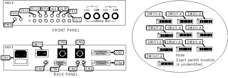
CONNECTIONS | |||
|
Function |
Label |
Function |
Label |
|
AC power |
CN1 |
E1 interface (BNC connector - transmit) |
CN6 |
|
TTL clock in (bantam jack) |
CN2 |
15-pin E1 network port |
CN7 |
|
T1 interface (bantam jack - receive) |
CN3 |
15-pin T1 network port |
CN8 |
|
T1 interface (bantam jack - transmit) |
CN4 |
9-pin serial port |
CN9 |
|
E1 interface (BNC connector - receive) |
CN5 |
Power switch |
SW11 |
|
USER CONFIGURABLE SETTINGS | |||
|
Setting |
Label |
Position | |
| » |
Factory configured - do not alter |
SW1/1 |
Off |
| » |
E1 Time slot 1 enabled |
SW1/2 |
On |
|
E1 Time slot 1 disabled |
SW1/2 |
Off | |
| » |
E1 Time slot 2 enabled |
SW1/3 |
On |
|
E1 Time slot 2 disabled |
SW1/3 |
Off | |
| » |
E1 Time slot 3 enabled |
SW1/4 |
On |
|
E1 Time slot 3 disabled |
SW1/4 |
Off | |
| » |
E1 Time slot 4 enabled |
SW1/5 |
On |
|
E1 Time slot 4 disabled |
SW1/5 |
Off | |
| » |
E1 Time slot 5 enabled |
SW1/6 |
On |
|
E1 Time slot 5 disabled |
SW1/6 |
Off | |
| » |
E1 Time slot 6 enabled |
SW1/7 |
On |
|
E1 Time slot 6 disabled |
SW1/7 |
Off | |
| » |
E1 Time slot 7 enabled |
SW1/8 |
On |
|
E1 Time slot 7 disabled |
SW1/8 |
Off | |
| » |
E1 Time slot 8 enabled |
SW2/1 |
On |
|
E1 Time slot 8 disabled |
SW2/1 |
Off | |
| » |
E1 Time slot 9 enabled |
SW2/2 |
On |
|
E1 Time slot 9 disabled |
SW2/2 |
Off | |
| » |
E1 Time slot 10 enabled |
SW2/3 |
On |
|
E1 Time slot 10 disabled |
SW2/3 |
Off | |
| » |
E1 Time slot 11 enabled |
SW2/4 |
On |
|
E1 Time slot 11 disabled |
SW2/4 |
Off | |
| » |
E1 Time slot 12 enabled |
SW2/5 |
On |
|
E1 Time slot 12 disabled |
SW2/5 |
Off | |
| » |
E1 Time slot 13 enabled |
SW2/6 |
On |
|
E1 Time slot 13 disabled |
SW2/6 |
Off | |
| » |
E1 Time slot 14 enabled |
SW2/7 |
On |
|
E1 Time slot 14 disabled |
SW2/7 |
Off | |
| » |
E1 Time slot 15 enabled |
SW2/8 |
On |
|
E1 Time slot 15 disabled |
SW2/8 |
Off | |
| » |
E1 Time slot 16 disabled |
SW3/1 |
Off |
|
E1 Time slot 16 enabled |
SW3/1 |
On | |
| » |
E1 Time slot 17 enabled |
SW3/2 |
On |
|
E1 Time slot 17 disabled |
SW3/2 |
Off | |
| » |
E1 Time slot 18 enabled |
SW3/3 |
On |
|
E1 Time slot 18 disabled |
SW3/3 |
Off | |
| » |
E1 Time slot 19 enabled |
SW3/4 |
On |
|
E1 Time slot 19 disabled |
SW3/4 |
Off | |
| » |
E1 Time slot 20 enabled |
SW3/5 |
On |
|
E1 Time slot 20 disabled |
SW3/5 |
Off | |
| » |
E1 Time slot 21 enabled |
SW3/6 |
On |
|
E1 Time slot 21 disabled |
SW3/6 |
Off | |
| » |
E1 Time slot 22 enabled |
SW3/7 |
On |
|
E1 Time slot 22 disabled |
SW3/7 |
Off | |
| » |
E1 Time slot 23 enabled |
SW3/8 |
On |
|
E1 Time slot 23 disabled |
SW3/8 |
Off | |
|
USER CONFIGURABLE SETTINGS (CONT.) | |||
|
» E1 Time slot 24 enabled |
SW4/1 |
On | |
|
E1 Time slot 24 disabled |
SW4/1 |
Off | |
| » |
E1 Time slot 25 disabled |
SW4/2 |
Off |
|
E1 Time slot 25 enabled |
SW4/2 |
On | |
| » |
E1 Time slot 26 disabled |
SW4/3 |
Off |
|
E1 Time slot 26 enabled |
SW4/3 |
On | |
| » |
E1 Time slot 27 disabled |
SW4/4 |
Off |
|
E1 Time slot 27 enabled |
SW4/4 |
On | |
| » |
E1 Time slot 28 disabled |
SW4/5 |
Off |
|
E1 Time slot 28 enabled |
SW4/5 |
On | |
| » |
E1 Time slot 29 disabled |
SW4/6 |
Off |
|
E1 Time slot 29 enabled |
SW4/6 |
On | |
| » |
E1 Time slot 30 disabled |
SW4/7 |
Off |
|
E1 Time slot 30 enabled |
SW4/7 |
On | |
| » |
E1 Time slot 31 disabled |
SW4/8 |
Off |
|
E1 Time slot 31 enabled |
SW4/8 |
On | |
| » |
T1 Time slot 0 is data channel |
SW5/1 |
Off |
|
T1 Time slot 0 is voice channel |
SW5/1 |
On | |
| » |
T1 Time slot 1 is data channel |
SW5/2 |
Off |
|
T1 Time slot 1 is voice channel |
SW5/2 |
On | |
| » |
T1 Time slot 2 is data channel |
SW5/3 |
Off |
|
T1 Time slot 2 is voice channel |
SW5/3 |
On | |
| » |
T1 Time slot 3 is data channel |
SW5/4 |
Off |
|
T1 Time slot 3 is voice channel |
SW5/4 |
On | |
| » |
T1 Time slot 4 is data channel |
SW5/5 |
Off |
|
T1 Time slot 4 is voice channel |
SW5/5 |
On | |
| » |
T1 Time slot 5 is data channel |
SW5/6 |
Off |
|
T1 Time slot 5 is voice channel |
SW5/6 |
On | |
| » |
T1 Time slot 6 is data channel |
SW5/7 |
Off |
|
T1 Time slot 6 is voice channel |
SW5/7 |
On | |
| » |
T1 Time slot 7 is data channel |
SW5/8 |
Off |
|
T1 Time slot 7 is voice channel |
SW5/8 |
On | |
| » |
T1 Time slot 8 is data channel |
SW6/1 |
Off |
|
T1 Time slot 8 is voice channel |
SW6/1 |
On | |
| » |
T1 Time slot 9 is data channel |
SW6/2 |
Off |
|
T1 Time slot 9 is voice channel |
SW6/2 |
On | |
| » |
T1 Time slot 10 is data channel |
SW6/3 |
Off |
|
T1 Time slot 10 is voice channel |
SW6/3 |
On | |
| » |
T1 Time slot 11 is data channel |
SW6/4 |
Off |
|
T1 Time slot 11 is voice channel |
SW6/4 |
On | |
| » |
T1 Time slot 12 is data channel |
SW6/5 |
Off |
|
T1 Time slot 12 is voice channel |
SW6/5 |
On | |
| » |
T1 Time slot 13 is data channel |
SW6/6 |
Off |
|
T1 Time slot 13 is voice channel |
SW6/6 |
On | |
| » |
T1 Time slot 14 is data channel |
SW6/7 |
Off |
|
T1 Time slot 14 is voice channel |
SW6/7 |
On | |
| » |
T1 Time slot 15 is data channel |
SW6/8 |
Off |
|
T1 Time slot 15 is voice channel |
SW6/8 |
On | |
|
USER CONFIGURABLE SETTINGS (CONT.) | |||
|
» T1 Time slot 16 is data channel |
SW7/1 |
Off | |
|
T1 Time slot 16 is voice channel |
SW7/1 |
On | |
| » |
T1 Time slot 17 is data channel |
SW7/2 |
Off |
|
T1 Time slot 17 is voice channel |
SW7/2 |
On | |
| » |
T1 Time slot 18 is data channel |
SW7/3 |
Off |
|
T1 Time slot 18 is voice channel |
SW7/3 |
On | |
| » |
T1 Time slot 19 is data channel |
SW7/4 |
Off |
|
T1 Time slot 19 is voice channel |
SW7/4 |
On | |
| » |
T1 Time slot 20 is data channel |
SW7/5 |
Off |
|
T1 Time slot 20 is voice channel |
SW7/5 |
On | |
| » |
T1 Time slot 21 is data channel |
SW7/6 |
Off |
|
T1 Time slot 21 is voice channel |
SW7/6 |
On | |
| » |
T1 Time slot 22 is data channel |
SW7/7 |
Off |
|
T1 Time slot 22 is voice channel |
SW7/7 |
On | |
| » |
T1 Time slot 23 is data channel |
SW7/8 |
Off |
|
T1 Time slot 23 is voice channel |
SW7/8 |
On | |
| » |
T1 B8ZS line code enabled |
SW8/1 |
Off |
|
T1 AMI line code enabled |
SW8/1 |
On | |
| » |
T1 SF(D4) frame mode enabled |
SW8/2 |
Off |
|
T1 ESF frame mode enabled |
SW8/2 |
On | |
| » |
T1 jitter attenuator enabled |
SW8/6 |
On |
|
T1 jitter attenuator disabled |
SW8/6 |
Off | |
| » |
T1 jitter on received side |
SW8/7 |
Off |
|
T1 jitter on transmitted side |
SW8/7 |
On | |
| » |
Factory configured - do not alter |
SW8/8 |
Off |
| » |
Factory configured - do not alter |
SW9/1 |
Off |
| » |
E1 CRC4 disabled |
SW9/2 |
Off |
|
E1 CRC4 enabled |
SW9/2 |
On | |
| » |
E1 CCS(PCM31) frame mode enabled |
SW9/3 |
Off |
|
E1 CAS(PCM30) frame mode enabled |
SW9/3 |
On | |
| » |
E1 jitter attenuator enabled |
SW10/4 |
On |
|
E1 jitter attenuator disabled |
SW10/4 |
Off | |
| » |
E1 jitter on receive side |
SW10/5 |
Off |
|
E1 jitter on transmit side |
SW10/5 |
On | |
| » |
Factory configured - do not alter |
SW10/6 |
On |
| » |
Factory configured - do not alter |
SW10/7 |
Off |
| » |
Factory configured - do not alter |
SW10/8 |
Off |
|
LINE ATTENUATION & CABLE LENGTH SELECTION | |||||
|
DSX |
CSU |
S8/3 |
S8/4 |
S8/5 | |
| » |
0 - 133 feet |
0dB |
Off |
Off |
Off |
|
133 - 266 feet |
N/A |
On |
Off |
Off | |
|
266 - 399 feet |
N/A |
Off |
On |
Off | |
|
399 - 533 feet |
N/A |
On |
On |
Off | |
|
533 - 655 feet |
N/A |
Off |
Off |
On | |
|
N/A |
-7.5dB |
On |
Off |
On | |
|
N/A |
-15dB |
Off |
On |
On | |
|
N/A |
-22.5dB |
On |
On |
On | |
|
E1 LINE IMPEDANCE | ||||||
|
Setting |
SW9/4 |
SW9/5 |
SW9/6 |
SW9/7 |
SW9/8 | |
| » |
75 Ohm operation |
Off |
Off |
Off |
On |
On |
|
120 Ohm operation |
On |
On |
On |
Off |
Off | |
|
CLOCK MODE | ||||
|
Timing Source |
SW10/1 |
SW10/2 |
SW10/3 | |
| » |
Transparent |
Off |
Off |
Off |
|
E1 side recovery |
On |
Off |
Off | |
|
Internal oscillator 2048Khz |
Off |
On |
Off | |
|
External 2048Khz |
On |
On |
Off | |
|
Loopback |
Off |
Off |
On | |
|
T1 side recovery |
On |
Off |
On | |
|
Internal oscillator 1544Khz |
Off |
On |
On | |
|
External 1544Khz |
On |
On |
On | |
|
DIAGNOSTIC LED(S) | |||
|
LED |
Color |
Status |
Condition |
|
PWR |
Green |
On |
Power is on |
|
PWR |
Green |
Off |
Power is off |
|
FAIL |
Red |
On |
System failure detected |
|
FAIL |
Red |
Off |
System failure not detected |
|
SGLS |
Red |
On |
Receive signal loss detected |
|
SGLS |
Red |
Off |
Receive signal loss not detected |
|
SCLS |
Red |
On |
Loss of received frame syncronization detected |
|
SCLS |
Red |
Off |
Loss of received frame syncronization not detected |
|
BPV |
Red |
On |
Bipolar coding violation has been detected on network |
|
BPV |
Red |
Off |
Bipolar coding violation has not been detected on network |
|
AIS |
Red |
On |
All ones signal is being received on network line |
|
AIS |
Red |
Off |
All ones signal is not being received on network line |
|
SLIP |
Red |
On |
Elastic buffer slip has occurred |
|
SLIP |
Red |
Off |
Elastic buffer slip has not occurred |
|
YEL |
Red |
On |
Yellow alarm condition has been detected on network |
|
YEL |
Red |
Off |
Yellow alarm condition has not been detected on network |
|
TST |
Red |
On |
Device is conducting a loopback test |
|
TST |
Red |
Off |
Device is not conducting a loopback test |
|
Note: Top row of LEDs indicate E1 network activity. Bottom row indicates T1 network activity | |||
|
MISCELLANEOUS TECHNICAL NOTES |
|
Timeslot switches are ignored in unframe mode. In framed mode, clock rate is determined by the number of timeslots enabled ( n ). In CAS mode, SW3/1 must be set to off position or a loopback test will occur. Cascading units must not be assigned identical or overlapping timeslots. |