HAYES MICROCOMPUTER PRODUCTS, INC.
ULTRA SMARTMODEM 9600
|
Card Type |
Fax, Modem (synchronous/asynchronous) |
|
Chip Set |
Unidentified |
|
Maximum Data Rate |
9600bps |
|
Data Bus |
External |
|
Data Modulation Protocol |
Bell 103/212A ITU-T V.21, V.22, V.22bis, V.23, V.32 |
|
Error Correction/Compression |
Adaptive data compression, V-series LAPB, MNP5, V.42, V.42bis, X.25 |
|
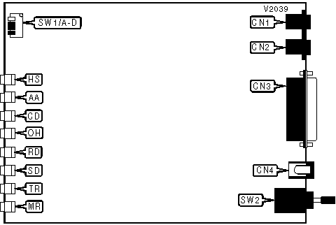
CONNECTIONS | ||||||
|
Function |
Label |
Function |
Label | |||
|
Line in |
CN1 |
DC power |
CN4 | |||
|
Line out |
CN2 |
Power switch |
SW2 | |||
|
RS-232/422 |
CN3 | |||||
|
COMMAND SET SELECTION | ||
|
Setting |
SW1/C |
SW1/D |
|
AT commands only |
Up |
Up |
|
Asynchronous V.25bis |
Up |
Down |
|
Synchronous V.25bis HDLC framing |
Down |
Up |
|
Synchronous V.25bis Character framing |
Down |
Down |
|
Note: Our normal convention for switches is On/Off, this document will use Up/Down. | ||
|
USER CONFIGURABLE SETTINGS | ||
|
Setting |
Label |
Position |
|
Command recognition enabled/smart mode |
SW1/A |
Up |
|
Command recognition disabled/dumb mode |
SW1/A |
Down |
|
Carrier signal adjustment disabled |
SW1/B |
Up |
|
Carrier signal adjustment enabled |
SW1/B |
Down |
|
Note: Our normal convention for switches is On/Off, this document will use Up/Down. | ||
|
DIAGNOSTIC LED(S) | |||
|
LED |
Color |
Status |
Condition |
|
HS |
Red |
On |
Modem is operating at 4800bps or faster |
|
HS |
Red |
Off |
Modem is operating at slower than 4800bps |
|
AA |
Red |
On |
Auto-answer enabled/ring indicated when Auto-answer disabled |
|
AA |
Red |
Off |
Auto-answer disabled/ring indicated when Auto-answer enabled |
|
CD |
Red |
On |
Carrier signal detected |
|
CD |
Red |
Off |
Carrier signal not detected |
|
OH |
Red |
On |
Modem is off-hook |
|
OH |
Red |
Off |
Modem is on-hook |
|
RD |
Red |
On |
Modem is receiving data |
|
RD |
Red |
Off |
Modem is not receiving data |
|
SD |
Red |
On |
Modem is transmitting data |
|
SD |
Red |
Off |
Modem is not transmitting data |
|
TR |
Red |
On |
DTR signal is high |
|
TR |
Red |
Off |
DTR signal is low |
|
MR |
Red |
On |
Power is on |
|
MR |
Red |
Off |
Power is off |
|
MR |
Red |
Blinking |
Self-test or diagnostic mode enabled |
Proprietary AT Command Set
|
DIAL | |
|
Type: |
Immediate |
|
Format: |
AT [cmds] D<#> [cmds] |
|
Description: |
Dials telephone number according to any modifiers included in the string |
|
Note: |
Any combination of modifiers can be used to produce the desired dial functions in sequence. |
|
Modifier |
Function |
|
P |
Pulse dialing enabled |
|
R |
Answer mode enabled, originate mode disabled following handshake initiation. |
|
S=n |
Dial stored telephone number n |
|
T |
Tone dialing enabled |
|
W |
Dialing resumed following dial tone detection |
|
, |
Dialing paused for amount of time specified in S8 register |
|
! |
Modem commanded to go off-hook for specified time before returning on-hook. |
|
@ |
Wait for quiet answer |
|
; |
Modem returned to command state after dialing |
|
REPORT INFORMATION | |
|
Type: |
Immediate |
|
Format: |
AT [cmds] In [cmds] |
|
Description: |
Displays information requested |
|
Command |
Function |
|
I0 |
Reports product code |
|
I1 |
Reports ROM checksum |
|
I2 |
Tests and reports ROM checksum |
|
BUFFER SIZE - LOWER LIMIT | |
|
Type: |
Register |
|
Format: |
AT [cmds] S49=n [cmds] |
|
Default: |
8 |
|
Range: |
1-249 |
|
Unit: |
1 byte |
|
Description: |
Controls the low-end size of the buffer during error-control or auto-speed buffering mode |
|
BUFFER SIZE - UPPER LIMIT | |
|
Type: |
Register |
|
Format: |
AT [cmds] S50=n [cmds] |
|
Default: |
16 |
|
Range: |
2-250 |
|
Unit: |
1 byte |
|
Description: |
Controls the high-end size of the buffer during error-control or auto-speed buffering mode |
|
LEASED LINE ATTENUATION LEVEL | |
|
Type |
Register |
|
Format |
AT [cmds] S63=n [cmds] |
|
Default |
0 |
|
Range |
0-15 |
|
Unit |
-1 dBm |
|
Description |
Sets the power level for transmission over leased lines |
|
FRAME LIMIT | |
|
Type |
Register |
|
Format |
AT [cmds] S69=n [cmds] |
|
Default: |
15 |
|
Range: |
0-15 |
|
Unit: |
1 frame |
|
Description: |
Sets the maximum number of packets that may be sent without acknowledgment by the remote system. |
|
Note: |
LAPM connections use a maximum of 15 frames. LAPB and X.25 connections use a maximum of 8 frames. |
|
FRAME RE-TRANSMISSION | |
|
Type |
Register |
|
Format |
AT [cmds] S70=n [cmds] |
|
Default: |
10 |
|
Range: |
0-255 |
|
Unit: |
1 frame |
|
Description: |
Sets the limit for the number of re-transmissions the local modem attempts when an error-control mechanism detects frame transmission data errors. After the re-transmission limit has been reached, the modem initiates the hang-up process. |
|
LINK LAYER TIMER | |
|
Type |
Register |
|
Format |
AT [cmds] S71=n [cmds] |
|
Default: |
2 |
|
Range: |
1-255 |
|
Unit: |
.1 second |
|
Description: |
Sets the maximum duration the local modem waits for a response after sending the link layer. If no response is received within LINKLIMIT (see note), the local modem re-transmits the link layer. |
|
Note: |
The duration is determined according to the formula: LINKLIMIT = 2(maximum packet size + 11)(8 + line speed[bps]) + S71 + 500 ms |
|
FLAG IDLE TIMER | |
|
Type |
Register |
|
Format |
AT [cmds] S72=n [cmds] |
|
Default: |
30 |
|
Range: |
1-255 |
|
Unit: |
1 second |
|
Description: |
Sets the maximum duration the modem waits after detecting loss of both data and flag-idle signals. When the maximum duration is reached, the modem initiates the hang-up process. A value of 0 in S72 allows an indefinite wait. |
|
DATA LOSS TIMER | |
|
Type |
Register |
|
Format |
AT [cmds] S73=n [cmds] |
|
Default: |
5 |
|
Range: |
1-255 |
|
Unit: |
1 second |
|
Description: |
Sets the maximum duration the modem waits after detecting loss of data while receiving good carrier and flag idle signals. When the maximum duration is reached, the local modem sends a query to the remote modem to determine if it is operating properly. When the value calculated for QUERYLIMIT is reached (see note), the modem initiates the hang-up process. |
|
Note: |
The local modem will send the query several times according to the formula: QUERYLIMIT= 2(LINKLIMIT)(S73) seconds The value for LINKLIMIT is defined in S71. |
|
ASU NEGOTIATION | |
|
Type |
Register |
|
Format |
AT [cmds] S84=n [cmds] |
|
Description: |
Sets the Adaptive Start-Up (ASU) negotiation method |
|
Command |
Function |
|
S84=0 |
ASU disabled |
|
S84=128 |
Fixed startup |
|
í S84=129 |
Both local and remote modems use fast startup |
|
S84=130 |
Both local and remote modems use smooth startup |
|
S84=131 |
Local modem uses fast startup, remote uses smooth startup |
|
S84=132 |
Local modem uses smooth startup, remote uses fast startup |
|
ASU NEGOTIATION REPORT | |
|
Type |
Register |
|
Format |
AT [cmds] S85? [cmds] |
|
Description: |
Reports the Adaptive Start-Up (ASU) negotiation method |
|
Value |
Meaning |
|
0 |
ASU disabled |
|
128 |
Fixed startup |
|
í 129 |
Both local and remote modems use fast startup |
|
130 |
Both local and remote modems use smooth startup |
|
131 |
Local modem uses fast startup, remote uses smooth startup |
|
132 |
Local modem uses smooth startup, remote uses fast startup |
|
MI/MIC | |
|
Type |
Register |
|
Format |
AT [cmds] S92=n [cmds] |
|
Description: |
Controls the Mode Indicate/Mode Indicate Common (MI/MIC) interface. |
|
Command |
Function |
|
í S92=0 |
MI/MIC disabled |
|
S92=1 |
Level triggered, originate mode, ring indicator pulse enabled |
|
S92=3 |
Edge triggered, originate mode, ring indicator pulse enabled |
|
S92=5 |
Level triggered, answer mode, ring indicator pulse enabled |
|
S92=7 |
Edge triggered, answer mode, ring indicator pulse enabled |
|
S92=9 |
Level triggered, originate mode, ring indicator pulse disabled |
|
S92=11 |
Edge triggered, originate mode, ring indicator pulse disabled |
|
S92=13 |
Level triggered, answer mode, ring indicator pulse disabled |
|
S92=15 |
Edge triggered, answer mode, ring indicator pulse disabled |
|
V.25bis DTE SPEED | |
|
Type |
Register |
|
Format |
AT [cmds] S93=n [cmds] |
|
Description: |
Sets the speed of the local serial port when in V.25bis mode. |
|
Command |
Function |
|
S93=3 |
300bps |
|
S93=5 |
1200bps |
|
S93=6 |
2400bps |
|
S93=7 |
4800bps |
|
í S93=9 |
9600bps |
|
COMMAND SET OPTIONS | ||
|
Type |
Register | |
|
Format |
AT [cmds] S94=n [cmds] | |
|
Default: |
0 | |
|
Range: |
0-15 | |
|
Unit: |
Bit-mapped | |
|
Description: |
Sets various options for command set modes | |
|
Bit |
Value |
Function |
|
1, 0 |
00 01 10 11 |
Use AT command set Use asynchronous V.25 command set Use synchronous V.25 command set with HDLC framing Use synchronous V.25 command set with character framing |
|
2 |
0 1 |
Addressed calling Direct access calling |
|
3 |
0 1 |
Use ASCII character set Use EBCDIC character set |
|
PAD CONFIGURATION | ||
|
Type: |
Register | |
|
Format: |
AT [cmds] S53=n [cmds] | |
|
Description: |
Sets various options for the X.25 Packet Assembler/Disassembler. | |
|
Command |
Function | |
|
S53=0 |
CCITT compatibility | |
|
S53=1 |
CCITT compatibility, display channel number before PAD prompt ( 1* ) | |
|
í S53=2 |
Fixed user interface, PAD prompt hyphen ( - ) | |
|
S53=3 |
Fixed user interface, display channel number before PAD prompt ( 1- ) | |
|
S53=4 |
Fixed control interface, PAD prompt hyphen | |
|
S53=5 |
Fixed control interface, display channel number before PAD prompt | |
|
S53=6 |
Fixed user and fixed control interface, PAD prompt hyphen | |
|
S53=7 |
Fixed user and fixed control interface, display channel number before PAD prompt | |
|
MINIMUM INCOMING LCN | |
|
Type |
Register |
|
Format |
AT [cmds] S74=n S75=n [cmds] |
|
Default: |
0 (S74), 0 (S75) |
|
Range: |
1-40 (S74), 1-99 (S75) |
|
Unit: |
None |
|
Description: |
These registers set the lowest Logical Channel Number (LCN) that the packet driver will attempt to answer calls on. The address itself may range from 0 - 4095. |
|
Note: |
The address is determined by the formula: ADDRESS = S74 * 100 + S75 |
|
MAXIMUM INCOMING LCN | |
|
Type |
Register |
|
Format |
AT [cmds] S76=n S77=n [cmds] |
|
Default: |
40 (S76), 95 (S77) |
|
Range: |
1-40 (S76), 1-99 (S77) |
|
Unit: |
None |
|
Description: |
These registers set the highest Logical Channel Number (LCN) that the packet driver will attempt to answer calls on. The address itself may range from 0 - 4095. |
|
Note: |
The address is determined by the formula: ADDRESS = S76 * 100 + S77 |
|
OUTGOING LCN | |
|
Type |
Register |
|
Format |
AT [cmds] S78=n S79=n [cmds] |
|
Default: |
0 (S78), 16 (S79) |
|
Range: |
1-40 (S78), 1-99 (S79) |
|
Unit: |
None |
|
Description: |
These registers set the Logical Channel Number (LCN) that the packet driver will place calls on. The address itself may range from 0 - 4095. |
|
Note: |
The address is determined by the formula: ADDRESS = S78 * 100 + S79 |
|
RESTART REQUEST | |
|
Format |
AT [cmds] S80=n [cmds] |
|
Default: |
1 |
|
Range: |
0-255 |
|
Unit: |
None |
|
Description: |
Sets the maximum number of retransmission requests |
|
ACKNOWLEDGMENT WAIT TIMER | |
|
Type: |
Register |
|
Format |
AT [cmds] S81=n [cmds] |
|
Default: |
18 |
|
Range: |
0-255 |
|
Unit: |
10 seconds |
|
Description: |
Maximum time the modem will wait for acknowledgment of a request for retransmission before it initiates recovery. |