HAYES MICROCOMPUTER PRODUCTS, INC.
ACCURA ISDN
|
Card Type |
ISDN TA |
|
Chipset |
Siemens |
|
ISDN Protocol |
V.110, V.120, X.75, PPP |
|
Switch Type |
5ESS, DMS100, 1TR6, EWSD, DSS1, NI-1 |
|
Data Bus |
Serial |
|
Error Correction/Compression |
V.42bis |
|
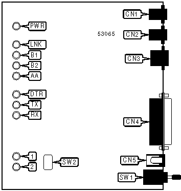
CONNECTIONS | |||
|
Function |
Label |
Function |
Label |
|
Analog line 1 in |
CN1 |
DC power in |
CN5 |
|
Analog line 2 in |
CN2 |
Power switch |
SW1 |
|
ISDN line out |
CN3 |
Auto-dial switch |
SW2 |
|
Serial port |
CN4 | ||
Note: Pressing the auto-dial switch while connected will disconnect the call. | |||
|
DIAGNOSTIC LED(S) (POWER-UP) | |||
|
LED |
Color |
Status |
Condition |
|
LNK |
Unidentified |
On |
TA is testing memory |
|
LNK |
Unidentified |
Blinking |
Memory test failed |
|
B1 |
Unidentified |
On |
TA is testing ISDN controller interface |
|
B1 |
Unidentified |
Blinking |
ISDN controller interface test failed |
|
B2 |
Unidentified |
On |
TA is testing ISDN controller functions |
|
B2 |
Unidentified |
Blinking |
ISDN controller function test failed |
|
AA |
Unidentified |
On |
TA is testing HDLC functions |
|
AA |
Unidentified |
Blinking |
HDLC function test failed |
|
LNK |
Unidentified |
On |
All tests passed |
Note: On power-up, the TA should go through the tests in the order indicated above. A blinking LED or any pattern other than the ones shown above indicate an error. | |||
|
DIAGNOSTIC LED(S) (NORMAL OPERATION) | |||
|
LED |
Color |
Status |
Condition |
|
PWR |
Unidentified |
On |
Power is on |
|
PWR |
Unidentified |
Off |
Power is off |
|
LNK |
Unidentified |
On |
Physical ISDN layer active |
|
LNK |
Unidentified |
Off |
Physical ISDN layer inactive |
|
LNK |
Unidentified |
Blinking |
D-channel link layer in multi-frame mode |
|
B1 |
Unidentified |
On |
B1 channel connected |
|
B1 |
Unidentified |
Off |
B1 channel not connected |
|
B1 |
Unidentified |
Random blink |
B1 channel is retransmitting packets |
|
B1 |
Unidentified |
1 blink |
B1 channel is protected by single DES encryption |
|
B1 |
Unidentified |
3 blinks |
B1 channel is protected by triple DES encryption |
|
B2 |
Unidentified |
On |
B2 channel connected |
|
B2 |
Unidentified |
Off |
B2 channel not connected |
|
B2 |
Unidentified |
Random blink |
B2 channel is retransmitting packets |
|
B2 |
Unidentified |
1 blink |
B2 channel is protected by single DES encryption |
|
B2 |
Unidentified |
3 blinks |
B2 channel is protected by triple DES encryption |
|
AA |
Unidentified |
On |
Auto-answer enabled |
|
AA |
Unidentified |
Off |
Auto-answer disabled |
|
AA |
Unidentified |
Blinking |
Phone is ringing |
|
DTR |
Unidentified |
On |
DTR signal is high |
|
DTR |
Unidentified |
Off |
DTR signal is low |
|
TX |
Unidentified |
Blinking |
Serial port is transmitting data to TA |
|
TX |
Unidentified |
Off |
Serial port is not transmitting data to TA |
|
RX |
Unidentified |
Blinking |
Serial port is receiving data from TA |
|
RX |
Unidentified |
Off |
Serial port is not receiving data from TA |
|
1 |
Unidentified |
On |
Analog line 1 is off-hook |
|
1 |
Unidentified |
Off |
Analog line 1 is on-hook |
|
2 |
Unidentified |
On |
Analog line 2 is off-hook |
|
2 |
Unidentified |
Off |
Analog line 2 is on-hook |
|
SUPPORTED STANDARD COMMANDS |
|
Basic AT Commands |
|
+++, ‘comma’, A/ |
|
A, E, L, M, O, V |
|
&C, &D, &F, &W, &Z |
|
S-Registers |
|
S0, S1, S2, S3, S4, S5, S7, S8 |
Note: See MHI help file for complete information. |
Proprietary AT Command Set
|
ADDRESS IDENTIFICATION | |
|
Type: |
Immediate |
|
Format: |
AT [cmds] &ZOy=YaNb<#>/Zcxxxx/ [cmds]AT [cmds] &ZOy=A/Zcxxxx/ [cmds] |
|
Description: |
Sets the modem’s call identification to identify itself to remote ISDN devices. A indicates that no number is specified. |
|
Note: |
One of either the YaNb <#> arguments or the A/Zcxxxx/ must be present. |
|
Argument |
Function |
|
y=A |
Set address for analog adapter 1. |
|
y=B |
Set address for analog adapter 2. |
|
y=I |
Set address for ISDN. |
|
í a=0 |
Unknown number locality. |
|
a=1 |
International number. |
|
a=2 |
National number. |
|
a=3 |
Network number. |
|
a=4 |
Subscriber number. |
|
a=6 |
Abbreviated number. |
|
í b=0 |
Unknown number type. |
|
b=1 |
ISDN type number. |
|
b=3 |
X.121 data type number. |
|
b=8 |
National standard number. |
|
b=9 |
Private number. |
|
í c=0 |
NSAP subaddress of IA5 characters, AFI=0x50. |
|
c=2 |
User specified subaddress of IA5 characters. |
|
ADDRESS IDENTIFICATION - INCOMING CALL | |
|
Type: |
Immediate |
|
Format: |
AT [cmds] &ZIn= <#> [cmds] |
|
Description: |
Compares the number for an incoming call to the address stored for each value of n. If the numbers match, the call is routed to the appropriate mode and protocol. |
|
Argument |
Function |
|
n =0 |
Set address for X.75 ISDN. |
|
n =1 |
Set address for V.110 ISDN. |
|
n =2 |
Set address for V.120 ISDN. |
|
n =3 |
Set address for PPP asynchronous to HDLC conversion. |
|
n =4 |
Set address for protocol auto-detection. |
|
n =6 |
Set address for analog adapter 1. |
|
n =7 |
Set address for analog adapter 2. |
|
AUTO-ANSWER PRIORITY | |
|
Type: |
Configuration |
|
Format: |
AT [cmds] &Ln [cmds] |
|
Description: |
Selects which analog adapter will answer incoming analog calls first. |
|
Command |
Function |
|
í &L0 |
Analog adapter 1 answers first. |
|
&L1 |
Analog adapter 2 answers first. |
|
BANDWIDTH ON DEMAND - HIGH TRAFFIC THRESHOLD | |
|
Type: |
Register |
|
Format: |
AT [cmds] JAn [cmds] |
|
Default: |
48 |
|
Range: |
0 - 255 |
|
Unit: |
1 Kbps |
|
Description: |
Sets the level that the bandwidth in use must be over for the time set by the KAM and KAS commands for the TA to attempt to add another B channel connection. |
|
BANDWIDTH ON DEMAND - HIGH TRAFFIC TIME, MINUTES | |
|
Type: |
Register |
|
Format: |
AT [cmds] KAMn [cmds] |
|
Default: |
0 |
|
Range: |
0 - 63 |
|
Unit: |
1 minute |
|
Description: |
Sets the amount of time, in minutes, that the bandwidth in use set by the JA command must be exceeded for the TA to attempt to add another B channel connection. |
|
BANDWIDTH ON DEMAND - HIGH TRAFFIC TIME, SECONDS | |
|
Type: |
Register |
|
Format: |
AT [cmds] KASn [cmds] |
|
Default: |
0 |
|
Range: |
0 - 63 |
|
Unit: |
1 second |
|
Description: |
Sets the amount of time, in seconds, that the bandwidth in use set by the JA command must be exceeded for the TA to attempt to add another B channel connection. |
|
BANDWIDTH ON DEMAND - LOW TRAFFIC THRESHOLD | |
|
Type: |
Register |
|
Format: |
AT [cmds] JSn [cmds] |
|
Default: |
32 |
|
Range: |
0 - 255 |
|
Unit: |
1 Kbps |
|
Description: |
Sets the level that the bandwidth in use must be under for the time set by the KSM and KSS commands for the TA to drop a B channel connection. |
|
BANDWIDTH ON DEMAND - LOW TRAFFIC TIME, MINUTES | |
|
Type: |
Register |
|
Format: |
AT [cmds] KSMn [cmds] |
|
Default: |
0 |
|
Range: |
0 - 63 |
|
Unit: |
1 minute |
|
Description: |
Sets the amount of time, in minutes, that the bandwidth in use set by the JS command must be under for the TA to drop a B channel connection. |
|
BANDWIDTH ON DEMAND - LOW TRAFFIC TIME, SECONDS | |
|
Type: |
Register |
|
Format: |
AT [cmds] KSSn [cmds] |
|
Default: |
0 |
|
Range: |
0 - 63 |
|
Unit: |
1 second |
|
Description: |
Sets the amount of time, in seconds, that the bandwidth in use set by the JS command must be under for the TA to drop a B channel connection. |
|
BIT-MAPPED REGISTER S15 | ||
|
Format: |
AT [cmds] S15=n [cmds] | |
|
Default: |
130 | |
|
Range: |
0 - 158 | |
|
Description: |
Controls active profile and data format. | |
|
Bit |
Value |
Function |
|
1, 0 |
00 01 í 10 |
Use even parity. Use odd parity. Do not use parity. |
|
2 |
í 01 |
Use 1 stop bit. Use 2 stop bit. |
|
4, 3 |
í 0001 10 11 |
Use 10-bit characters. Use 11-bit characters. Use 9-bit characters. Use 8-bit characters. |
|
7, 6, 5 |
000 001 010 011 í 100 |
Profile 0 active at power-up. Profile 1 active at power-up. Profile 2 active at power-up. Profile 3 active at power-up. Factory defaults active at power-up. |
|
BIT-MAPPED REGISTER S21 | ||
|
Format: |
AT [cmds] S21=n [cmds] | |
|
Default: |
154 | |
|
Range: |
0 - 220 | |
|
Description: |
Controls DTR, CTS, CD, and DSR signals, and speaker options. | |
|
Bit |
Value |
Function |
|
0 |
0 |
Not used. |
|
2, 1 |
00 í 0110 |
Speaker disabled. Speaker enabled until carrier signal detected Speaker enabled. |
|
3 |
í 01 |
DSR forced high. DSR normal. |
|
4 |
0 í 1 |
CD forced high. CD normal. |
|
5 |
0 |
Not used. |
|
7, 6 |
00 01 í 1011 |
DTR is forced on. Dial default number on high DTR; hang up on low DTR. Low DTR hangs up and returns to command mode. Low DTR hangs up and resets the modem to profile 0. |
|
BIT-MAPPED REGISTER S23 | ||
|
Format: |
AT [cmds] S23=n [cmds] | |
|
Default: |
105 | |
|
Range: |
0 - 127 | |
|
Description: |
Controls result codes, dialing, and echo. | |
|
Bit |
Value |
Function |
|
0 |
0 í 1 |
Command echoing disabled. Command echoing enabled. |
|
1 |
0 |
Not used. |
|
2 |
í 01 |
Insertion during phone call disabled. Insertion during phone call enabled. |
|
5, 4, 3 |
000 001 010 011 100 í 101110 111 |
Basic result codes only enabled. Basic and connection speed result codes enabled. Basic and connection speed result codes and dialtone detection enabled. All result codes except dialtone detection enabled. All result codes enabled. All result codes plus DTE speed and error control level enabled. All result codes plus ARQ enabled. All result codes plus ARQ and error control level enabled. |
|
6 |
0 í 1 |
Display result codes in numeric form. Display result codes in long form. |
|
BIT-MAPPED REGISTER S35 | ||
|
Format: |
AT [cmds] S35=n [cmds] | |
|
Default: |
0 | |
|
Range: |
0 - 144 | |
|
Description: |
Controls 4800bps V.32, handshake interruption, V.26bis mode, leased line transmission attenuation, Selective Reject, password protection, and extended result codes. | |
|
Bit |
Value |
Function |
|
3 - 0 |
0000 |
Not used. |
|
4 |
í 01 |
Modem will not dial default number when Data/Voice button is pressed Modem will dial default number when Data/Voice button is pressed |
|
6, 5 |
00 |
Not used. |
|
7 |
í 01 |
Connection speed result codes disabled on error correcting connection. Connection speed result codes enabled on error correcting connection. |
|
BIT-MAPPED REGISTER S38 | ||
|
Format: |
AT [cmds] S38=n [cmds] | |
|
Default: |
0 | |
|
Range: |
0 - 9 | |
|
Description: |
Controls auto-dial and CD signal. | |
|
Bit |
Value |
Function |
|
0 |
í 01 |
Auto-dial of default number disabled. Auto-dial of default number enabled. |
|
2-1 |
00 |
Not used. |
|
3 |
í 01 |
CD normal. CD according to UNIX standard. |
|
BIT-MAPPED REGISTER S42 | ||
|
Format: |
AT [cmds] S42=n [cmds] | |
|
Default: |
0 | |
|
Range: |
0 - 104 | |
|
Description: |
Controls escape sequence, data/voice switch, and RING result codes. | |
|
Bit |
Value |
Function |
|
2 - 0 |
000 |
Not used. |
|
3 |
í 01 |
Escape sequence enabled in answer mode. Escape sequence disabled in answer mode. |
|
4 |
0 |
Not used. |
|
5 |
í 01 |
Data/Voice switch enabled. Data/Voice switch disabled. |
|
6 |
í 01 |
Enable RING result. Disable RING result. |
|
BIT-MAPPED REGISTER S44 | ||
|
Format: |
AT [cmds] S44=n [cmds] | |
|
Default: |
0 | |
|
Range: |
0 - 24 | |
|
Description: |
Controls cyclic dialing and DSR signal. | |
|
Bit |
Value |
Function |
|
3 |
í 01 |
Modem will dial only stored number specified by an executed DS command. Modem will cycle through stored numbers on DS command until modem connects. |
|
4 |
í 01 |
DSR normal. DSR follows DTR. |
|
BIT-MAPPED REGISTER S80 | ||
|
Format: |
AT [cmds] S80=n [cmds] | |
|
Default: |
0 | |
|
Range: |
0 - 208 | |
|
Description: |
Controls originate/answer mode and low-layer compatibility information. | |
|
Bit |
Value |
Function |
|
3 - 0 |
0000 |
Not used. |
|
4 |
í 01 |
Analog adapter 2 does not send low-level compatibility information. Analog adapter 2 sends low-level compatibility information. |
|
5 |
0 |
Not used. |
|
6 |
í 01 |
ISDN does not send low-level compatibility information. ISDN sends low-level compatibility information. |
|
7 |
í 01 |
Analog adapter 1 does not send low-level compatibility information. Analog adapter 1 sends low-level compatibility information. |
|
BIT-MAPPED REGISTER S83 | ||
|
Format: |
AT [cmds] S83=n [cmds] | |
|
Default: |
Unidentified | |
|
Range: |
0 - 53 | |
|
Description: |
Controls the Loopback 4 function, V.42bis compression, and the default dialing device. | |
|
Bit |
Value |
Function |
|
0 |
0 1 |
Loopback 4 disabled. Loopback 4 enabled. |
|
1 |
0 |
Not used. |
|
2 |
0 1 |
V.42bis compression disabled. V.42bis compression enabled. |
|
3 |
0 |
Not used. |
|
5, 4 |
í 0010 11 |
Originate calls with analog adapter 1 by default. Originate calls with ISDN by default. Originate calls with analog adapter 2 by default. |
|
BIT-MAPPED REGISTER S118 | ||
|
Format: |
AT [cmds] S118=n [cmds] | |
|
Default: |
Unidentified | |
|
Range: |
0 - 245 | |
|
Description: |
Controls dial-in mode, default line speed, low-speed service type, and analog call acceptance. | |
|
Bit |
Value |
Function |
|
0 |
0 1 |
Dial-in calls may be answered. Dial-in calls may not be answered. |
|
1 |
0 |
Not used. |
|
2 |
0 1 |
Use 64Kbps speed for ISDN. Use 56Kbps speed for ISDN. |
|
3 |
0 |
Not used. |
|
4 |
í 01 |
Use 3.1KHz service for analog line 2. Use voice service for analog line 2. |
|
5 |
í 01 |
Use 3.1KHz service for analog line 1. Use voice service for analog line 1. |
|
6 |
í 01 |
All analog calls will be answered. Only analog calls with matching MSN will be answered. |
|
7 |
í 01 |
Incoming analog calls will be answered. Incoming analog calls will be ignored. |
|
BIT-MAPPED REGISTER S119 | ||
|
Format: |
AT [cmds] S119=n [cmds] | |
|
Default: |
Unidentified | |
|
Range: |
0 - 54 | |
|
Description: |
Controls callback function, signalling DDI, call acceptance, V.110 minimum speed, and MSN function. | |
|
Bit |
Value |
Function |
|
0 |
í 01 |
Callback function disabled. Callback function enabled. |
|
1 |
í 01 |
Point-to-point signaling DDI function disabled. Point-to-point signaling DDI function enabled. |
|
2 |
í 01 |
Multipoint signaling DDI function disabled. Multipoint signaling DDI function enabled. |
|
3 |
í 01 |
All calls will be answered. Only calls with matching MSN will be answered. |
|
4 |
í 01 |
V.110 speed set to 19.2Kbps if local serial port speed is 19.2Kbps or faster. V.110 speed set to 38.4Kbps if local serial port speed is 38.4Kbps or faster. |
|
5 |
í 01 |
MSN functions normally. Treat MSN settings as subaddresses. |
|
CALL CHARGE - B1 | |
|
Type: |
Register |
|
Format: |
AT [cmds] S120? S121? [cmds] |
|
Default: |
Read-only |
|
Range: |
0-65535 |
|
Unit: |
N/A |
|
Description: |
These registers store the accumulated call charge for the first ISDN B channel. S120 stores the Most Significant Byte, and S121 stores the Least Significant Byte. To obtain the correct value, use S120 * 256 + S121. |
|
CALL CHARGE - B2 | |
|
Type: |
Register |
|
Format: |
AT [cmds] S122? S123? [cmds] |
|
Default: |
Read-only |
|
Range: |
0-65535 |
|
Unit: |
N/A |
|
Description: |
These registers store the accumulated call charge for the second ISDN B channel. S122 stores the Most Significant Byte, and S123 stores the Least Significant Byte. To obtain the correct value, use S122 * 256 + S123. |
|
CALLER ID | |
|
Type: |
Register |
|
Format: |
AT [cmds] S84=n [cmds] |
|
Description: |
Controls the Caller ID function of the TA. |
|
Command |
Function |
|
í S84=0 |
Caller ID enabled. |
|
S84=16 |
Caller ID disabled. |
|
CALLER ID INFORMATION | |
|
Type: |
Immediate |
|
Format: |
AT [cmds] *T [cmds] |
|
Description: |
Displays the last caller ID information. |
|
CHARACTER LENGTH | |
|
Type: |
Configuration |
|
Format: |
AT [cmds] *Cn [cmds] |
|
Description: |
Sets length of character. |
|
Command |
Function |
|
í *C0 |
Set 10-bit character. |
|
*C1 |
Set 11-bit character. |
|
*C2 |
Set 9-bit character. |
|
*C3 |
Set 8-bit character. |
|
COMPRESSION AND ERROR CORRECTION MODE | |
|
Type: |
Configuration |
|
Format: |
AT [cmds] &Knn [cmds] |
|
Description: |
Selects the type of data compression used over ISDN connections. |
|
Command |
Function |
|
&K00 |
Compression disabled for ISDN calls. |
|
&K44 |
V.42bis enabled for ISDN calls. |
|
CONFIGURATION PROFILES | |
|
Type: |
Immediate |
|
Format: |
AT [cmds] &Vn [cmds] |
|
Description: |
Displays active and stored configuration profiles. |
|
Command |
Function |
|
&V0 |
Displays current settings. |
|
&V1 |
Displays profile 0. |
|
&V2 |
Displays profile 1. |
|
&V3 |
Displays profile 2. |
|
&V4 |
Displays profile 3. |
|
&V5 |
Displays factory defaults. |
|
&V6 |
Displays analog adapter 1 settings. |
|
&V7 |
Displays analog adapter 2 settings. |
|
DEFAULT PHONE NUMBER | |
|
Type: |
Configuration |
|
Format: |
AT [cmds] *Dn [cmds] |
|
Default: |
0 |
|
Range: |
0-39 |
|
Unit: |
N/A |
|
Description: |
Sets the default phone number to memory location n. |
|
DEFAULT PHONE NUMBER | |
|
Type: |
Register |
|
Format: |
AT [cmds] S29=n [cmds] |
|
Default: |
0 |
|
Range: |
0-39 |
|
Unit: |
N/A |
|
Description: |
Sets the default phone number to memory location n. |
|
DES KEY SET | |
|
Type: |
Configuration |
|
Format: |
AT [cmds] CKxxxx [cmds] |
|
Description: |
Sets the key to be used for DES encryption. The key must be between 15 and 65 characters. |
|
DIAGNOSTICS | |
|
Type: |
Immediate |
|
Format: |
AT [cmds] CG [cmds] |
|
Description: |
Performs modem diagnostics. |
|
DIAL | |
|
Type: |
Immediate |
|
Format: |
AT [cmds] D <#>AT [cmds] DYaNb <#>/Zcxxxx/AT [cmds] DA/Zcxxxx/ |
|
Description: |
Dials telephone number according to any modifiers included in the string. |
|
Modifier |
Function |
|
DA |
Dial with analog adapter 1. |
|
DB |
Dial with analog adapter 2. |
|
DI |
Dial with ISDN. |
|
DL |
Re-dial last number. |
|
DSm+n |
Number in memory location m dialed. If n is also specified, TA will make a bundled call. |
|
DW |
Dialing resumed following dial tone detection. |
|
D, |
Dialing paused for amount of time specified in S8 register. |
|
N0 |
Unknown number type. |
|
N1 |
ISDN type number. |
|
N3 |
X.121 data type number. |
|
N8 |
National standard number. |
|
N9 |
Private number. |
|
Y0 |
Unknown number locality. |
|
Y1 |
International number. |
|
Y2 |
National number. |
|
Y3 |
Network number. |
|
Y4 |
Subscriber number. |
|
Y6 |
Abbreviated number. |
|
Z0 |
NSAP subaddress of IA5 characters, AFI=0x50. |
|
Z2 |
User specified subaddress of IA5 characters. |
|
DIALING MODE DEFAULT | |
|
Type: |
Configuration |
|
Format: |
AT [cmds] &On [cmds] |
|
Description: |
Selects which device the TA will originate calls with by default. |
|
Command |
Function |
|
&O0 |
Originate calls with analog adapter 2. |
|
&O2 |
Originate calls with ISDN. |
|
&O3 |
Originate calls with analog adapter 1. |
|
DISPLAY CALL CHARGE | |
|
Type: |
Immediate |
|
Format: |
AT [cmds] CH? [cmds] |
|
Description: |
Displays the number of charge units for the last call. |
|
DYNAMIC BANDWIDTH ALLOCATION | |
|
Type: |
Configuration |
|
Format: |
AT [cmds] CEn [cmds] |
|
Description: |
Selects whether dynamic bandwidth allocation will be used to allow simultaneous data and voice calls. |
|
Command |
Function |
|
CE0 |
Dynamic bandwidth allocation disabled. |
|
í CE1 |
Dynamic bandwidth allocation enabled. |
|
ENDPOINT DISCRIMINATOR ADDRESS | |
|
Type: |
Configuration |
|
Format: |
AT [cmds] EPD=<a,b,c,d...s,t> [cmds] |
|
Example: |
ATEPD=<284,254,124,62,5> |
|
Range: |
0 - 255 |
|
Description: |
Sets the endpoint discriminator address for multipoint PPP systems. Up to twenty numbers may be specified. |
|
FIRMWARE DOWNLOAD | |
|
Type: |
Immediate |
|
Format: |
AT [cmds] UPX |
|
Description: |
Begins an XMODEM download to the modem firmware. |
|
FLOW CONTROL | |
|
Type: |
Configuration |
|
Format: |
AT [cmds] &Hn [cmds] |
|
Description: |
Selects the type of flow control to use. |
|
Command |
Function |
|
&H0 |
Flow control disabled. |
|
í &H3 |
Hardware flow control enabled. |
|
&H4 |
Software flow control enabled. |
|
FLOW CONTROL | |
|
Type: |
Register |
|
Format: |
AT [cmds] S27=n [cmds] |
|
Description: |
Selects the type of flow control to use. |
|
Command |
Function |
|
S27=0 |
Flow control disabled. |
|
í S27=24 |
Hardware flow control enabled. |
|
S27=32 |
Software flow control enabled. |
|
FLOW CONTROL CHARACTER - XOFF | |
|
Type: |
Register |
|
Format: |
AT [cmds] S32=n [cmds] |
|
Default: |
19 |
|
Range: |
0-255 |
|
Unit: |
1 ASCII character |
|
Description: |
Sets the character used to represent XOFF. |
|
FLOW CONTROL CHARACTER - XON | |
|
Type: |
Register |
|
Format: |
AT [cmds] S31=n [cmds] |
|
Default: |
17 |
|
Range: |
0-255 |
|
Unit: |
1 ASCII character |
|
Description: |
Sets the character used to represent XON. |
|
HELP | |
|
Type: |
Immediate |
|
Format: |
AT [cmds] $ [cmds] |
|
Description: |
Displays help on the basic (no prefix) AT commands. |
|
HIGH LAYER COMPATIBILITY - ANALOG ADAPTER 1 | |
|
Type: |
Register |
|
Format: |
AT [cmds] S111=n [cmds] |
|
Description: |
Sets high layer compatibility information for analog adapter 1 in non-1TR6 modes. |
|
Note: |
This table should not be used in 1TR6 mode; see SERVICE INDICATOR DETAILS for settings. |
|
Command |
Function |
|
í S111=0 |
High layer compatibility information not sent. |
|
S111=1 |
HLC information set to telephone. |
|
S111=4 |
HLC information set to fax. |
|
S111=40 |
HLC information set to F.220 Teletex. |
|
S111=49 |
HLC information set to F.200 Teletex. |
|
S111=50 |
HLC information set to F.300/T110 video service. |
|
S111=53 |
HLC information set to F.60 telex. |
|
S111=56 |
HLC information set to X.400 message handling. |
|
S111=65 |
HLC information set to X.200 OSI application. |
|
HIGH LAYER COMPATIBILITY - ANALOG ADAPTER 2 | |
|
Type: |
Register |
|
Format: |
AT [cmds] S108=n [cmds] |
|
Description: |
Sets high layer compatibility information for analog adapter 2 in non-1TR6 modes. |
|
Note: |
This table should not be used in 1TR6 mode; see SERVICE INDICATOR DETAILS for settings. |
|
Command |
Function |
|
í S108=0 |
High layer compatibility information not sent. |
|
S108=1 |
HLC information set to telephone. |
|
S108=4 |
HLC information set to fax. |
|
S108=40 |
HLC information set to F.220 Teletex. |
|
S108=49 |
HLC information set to F.200 Teletex. |
|
S108=50 |
HLC information set to F.300/T110 video service. |
|
S108=53 |
HLC information set to F.60 telex. |
|
S108=56 |
HLC information set to X.400 message handling. |
|
S108=65 |
HLC information set to X.200 OSI application. |
|
HIGH LAYER COMPATIBILITY - ISDN INTERFACE | |
|
Type: |
Register |
|
Format: |
AT [cmds] S110=n [cmds] |
|
Description: |
Sets high layer compatibility information for the ISDN interface in non-1TR6 modes. |
|
Note: |
This table should not be used in 1TR6 mode; see SERVICE INDICATOR DETAILS for settings. |
|
Command |
Function |
|
í S110=0 |
High layer compatibility information not sent. |
|
S110=1 |
HLC information set to telephone. |
|
S110=4 |
HLC information set to fax. |
|
S110=40 |
HLC information set to F.220 Teletex. |
|
S110=49 |
HLC information set to F.200 Teletex. |
|
S110=50 |
HLC information set to F.300/T110 video service. |
|
S110=53 |
HLC information set to F.60 telex. |
|
S110=56 |
HLC information set to X.400 message handling. |
|
S110=65 |
HLC information set to X.200 OSI application. |
|
HOOK CONTROL | ||
|
Type: |
Immediate | |
|
Format: |
AT [cmds] Hn [cmds] | |
|
Description: |
Hangs up ISDN and analog lines. | |
|
Command |
Function | |
|
H0 |
Hangs up line currently in use. | |
|
H3 |
Hangs up analog line 1. | |
|
H4 |
Hangs up analog line 2. | |
|
HOOK FLASH TIME | |
|
Type: |
Register |
|
Format: |
AT [cmds] S56=n [cmds] |
|
Default: |
50 |
|
Range: |
0-255 |
|
Unit: |
10ms |
|
Description: |
Selects the amount of time the analog adapter goes on-hook for a hook flash. |
|
I-FIELD DATA LENGTH | |
|
Type: |
Register |
|
Format: |
AT [cmds] S114=n [cmds] AT [cmds] S115=n [cmds] |
|
Default: |
Unidentified |
|
Range: |
0-65535 |
|
Unit: |
N/A |
|
Description: |
These registers set the data length for the I-field. S114 stores the Most Significant Byte, and S115 stores the Least Significant Byte. To set the correct value for S114, use the formula S114 = INT(value/256). To set S115, use the formula S115 = value - S114 * 256. |
|
ISDN BUNDLE CONNECTION | |
|
Type: |
Configuration |
|
Format: |
AT [cmds] &Jn [cmds] |
|
Description: |
Selects when the modem will attempt to make a two-channel bundle connection. |
|
Command |
Function |
|
í &J0 |
Bundle connections disabled. |
|
&J1 |
Bundle connections enabled on answer only. |
|
&J2 |
Bundle connections enabled on originate only. |
|
&J3 |
Bundle connections enabled. |
|
ISDN BUNDLE CONNECTION | |
|
Type: |
Configuration |
|
Format: |
AT [cmds] S87=n [cmds] |
|
Description: |
Selects when the modem will attempt to make a two-channel bundle connection. |
|
Command |
Function |
|
í S87=0 |
Bundle connections disabled. |
|
S87=32 |
Bundle connections enabled on answer only. |
|
S87=64 |
Bundle connections enabled on originate only. |
|
S87=96 |
Bundle connections enabled. |
|
ISDN PACKET SIZE | |
|
Type: |
Configuration |
|
Format: |
AT [cmds] CLn [cmds] |
|
Default: |
252 |
|
Range: |
0-2048 |
|
Unit: |
1 byte |
|
Description: |
Sets the maximum packet size for transmitting data on the ISDN line. |
|
ISDN SPEED - B-CHANNEL | |
|
Type: |
Configuration |
|
Format: |
AT [cmds] &En [cmds] |
|
Description: |
Selects the base speed that will be used for ISDN B-channel communications. |
|
Command |
Function |
|
í &E0 |
64Kbps base speed. |
|
&E1 |
56Kbps base speed. |
|
LOCAL SERIAL PORT SPEED | |
|
Type: |
Register |
|
Format: |
AT [cmds] S18=n [cmds] |
|
Description: |
Sets serial port speed. |
|
Value |
Meaning |
|
0 |
Serial port speed follows connect speed. |
|
1 |
Sets 921.6Kbps speed. |
|
2 |
Sets 460.8Kbps speed. |
|
3 |
Sets 230.4Kbps speed. |
|
8 |
Sets 115.2Kbps speed. |
|
9 |
Sets 57.6Kbps speed. |
|
10 |
Sets 38.4Kbps speed. |
|
11 |
Sets 19.2Kbps speed. |
|
12 |
Sets 9600bps speed. |
|
13 |
Sets 4800bps speed. |
|
14 |
Sets 2400bps speed. |
|
15 |
Sets 1200bps speed. |
|
LOCAL SERIAL PORT SPEED ON AUTO-ANSWER | |
|
Type: |
Register |
|
Format: |
AT [cmds] S20=n [cmds] |
|
Description: |
Sets the speed of the local serial port when the modem auto-answers an incoming call. |
|
Value |
Meaning |
|
0 |
Sets 921.6Kbps speed. |
|
1 |
Sets 460.8Kbps speed. |
|
2 |
Sets 230.4Kbps speed. |
|
3 |
Sets 115.2Kbps speed. |
|
8 |
Sets 57.6Kbps speed. |
|
9 |
Sets 38.4Kbps speed. |
|
10 |
Sets 19.2Kbps speed. |
|
11 |
Sets 9600bps speed. |
|
12 |
Sets 4800bps speed. |
|
13 |
Sets 2400bps speed. |
|
14 |
Sets 1200bps speed. |
|
LOOPBACK 4 | |
|
Type: |
Configuration |
|
Format: |
AT [cmds] CPn [cmds] |
|
Description: |
Selects the Loopback 4 function. |
|
Command |
Function |
|
í CP0 |
Loopback 4 disabled. |
|
CP1 |
Loopback 4 enabled. |
|
LOOPBACK TEST SIGNALS | |
|
Type: |
Register |
|
Format: |
AT [cmds] S41=n [cmds] |
|
Description: |
Selects whether loopback test signals 140 and 141 on the RS-232 interface will be used. |
|
Command |
Function |
|
S41=0 |
Loopback test signals disabled. |
|
S41=8 |
Loopback test signals enabled. |
|
METERING PULSE | ||
|
Format: |
AT [cmds] S89=n [cmds] | |
|
Default: |
0 | |
|
Range: |
0 - 96 | |
|
Description: |
Selects whether the TA will generate metering pulses on either of the analog adapters. | |
|
Bit |
Value |
Function |
|
3 - 0 |
0000 |
Not used. |
|
5 |
í 01 |
Metering pulse disabled on analog adapter 2. Metering pulse enabled on analog adapter 2. |
|
6 |
í 01 |
Metering pulse disabled on analog adapter 1. Metering pulse enabled on analog adapter 1. |
|
PPP IDLE OUT PREVENTION | |
|
Type: |
Register |
|
Format: |
AT [cmds] S124=n [cmds] |
|
Default: |
0 |
|
Range: |
0-255 |
|
Unit: |
1 second |
|
Description: |
Sends an empty packet to avoid disconnection on PPP connections. |
|
PREFIX FOR INTERNATIONAL NUMBERS | |
|
Type: |
Configuration |
|
Format: |
AT [cmds] CIxxxx [cmds] |
|
Description: |
Sets the prefix that the modem will prepend to international numbers when reporting them in result codes. |
|
PREFIX FOR LONG-DISTANCE NUMBERS | |
|
Type: |
Configuration |
|
Format: |
AT [cmds] CNxxxx [cmds] |
|
Description: |
Sets the prefix that the modem will prepend to long-distance (but not international) numbers when reporting them in result codes. |
|
PROTOCOL/SPEED - ISDN B-CHANNEL | |
|
Type: |
Configuration |
|
Format: |
AT [cmds] Bnn [cmds] |
|
Description: |
Selects the protocol and speed that will be used for ISDN B-channel communications. |
|
Command |
Function |
|
B00 |
Use X.75 transparent. |
|
B01 |
Use X.75 with T.70. |
|
B04 |
Use X.75 with BTX. |
|
B10 |
Use V.110 autospeed. |
|
B13 |
Use V.110 at 2400bps. |
|
B14 |
Use V.110 at 4800bps. |
|
B15 |
Use V.110 at 9600bps. |
|
B16 |
Use V.110 at 14.4Kbps. |
|
B17 |
Use V.110 at 19.2Kbps. |
|
B18 |
Use V.110 at 38.4Kbps. |
|
B19 |
Use V.110 at 57.6Kbps. |
|
B20 |
Use V.120. |
|
B40 |
Use PPP asynchronous to HDLC conversion. |
|
PROTOCOL/SPEED - ISDN B-CHANNEL | |
|
Type: |
Register |
|
Format: |
AT [cmds] S82=n [cmds] |
|
Description: |
Selects the protocol and speed that will be used for ISDN B-channel communications. |
|
Command |
Function |
|
S82=60 |
Use V.120 at 64Kbps. |
|
S82=61 |
Use V.120 at 56Kbps. |
|
S82=62 |
Use X.75 transparent at 64Kbps. |
|
S82=63 |
Use X.75 transparent at 56Kbps. |
|
S82=64 |
Use X.75 with T.70 at 64Kbps. |
|
S82=65 |
Use X.75 with T.70 at 56Kbps. |
|
S82=70 |
Use X.75 with BTX at 64Kbps. |
|
S82=71 |
Use X.75 with BTX at 56Kbps. |
|
S82=72 |
Use V.110 at 64Kbps. |
|
S82=73 |
Use V.110 at 56Kbps. |
|
S82=74 |
Use PPP asynchronous to HDLC conversion at 64Kbps. |
|
S82=75 |
Use PPP asynchronous to HDLC conversion at 56Kbps. |
|
S82=76 |
Use SLIP asynchronous to HDLC conversion at 64Kbps. |
|
S82=77 |
Use SLIP asynchronous to HDLC conversion at 56Kbps. |
|
PROTOCOL/SPEED - ISDN B-CHANNEL BUNDLING | |
|
Type: |
Register |
|
Format: |
AT [cmds] S100=n [cmds] |
|
Description: |
Selects the protocol that will be used for ISDN B-channel bundling. |
|
Command |
Function |
|
í S100=0 |
Use Multiple Link Protocol. |
|
S100=1 |
Use cFossil Channel Bundling. |
|
PROTOCOL/SPEED - ISDN D-CHANNEL | |
|
Type: |
Configuration |
|
Format: |
AT [cmds] Pn [cmds] |
|
Description: |
Selects the protocol and speed that will be used for ISDN D-channel communications. |
|
Command |
Function |
|
í P0 |
Use Northern Telecom. |
|
P1 |
Use National ISDN for 1 SPID. |
|
P2 |
Use National ISDN for 2 SPIDs. |
|
P4 |
Use AT&T point-to-point. |
|
P5 |
Use AT&T multipoint for 1 SPID. |
|
P6 |
Use AT&T multipoint for 2 SPIDs. |
|
PROTOCOL/SPEED - ISDN D-CHANNEL | |
|
Type: |
Configuration |
|
Format: |
AT [cmds] S86=n [cmds] |
|
Description: |
Selects the protocol and speed that will be used for ISDN D-channel communications. |
|
Command |
Function |
|
í S86=0 |
Use Northern Telecom. |
|
S86=1 |
Use National ISDN for 1 SPID. |
|
S86=2 |
Use National ISDN for 2 SPIDs. |
|
S86=4 |
Use AT&T point-to-point. |
|
S86=5 |
Use AT&T multipoint for 1 SPID. |
|
S86=6 |
Use AT&T multipoint for 2 SPIDs. |
|
PROTOCOL/SPEED - OUTGOING ISDN | |
|
Type: |
Register |
|
Format: |
AT [cmds] S102=n [cmds] |
|
Description: |
Selects the protocol and speed that will be used for outgoing ISDN communications. |
|
Command |
Function |
|
S102=60 |
Use V.120 at 64Kbps. |
|
S102=61 |
Use V.120 at 56Kbps. |
|
S102=62 |
Use X.75 transparent at 64Kbps. |
|
S102=63 |
Use X.75 transparent at 56Kbps. |
|
S102=64 |
Use X.75 with T.70 at 64Kbps. |
|
S102=65 |
Use X.75 with T.70 at 56Kbps. |
|
S102=70 |
Use X.75 with BTX at 64Kbps. |
|
S102=71 |
Use X.75 with BTX at 56Kbps. |
|
S102=72 |
Use V.110 at 64Kbps. |
|
S102=73 |
Use V.110 at 56Kbps. |
|
S102=74 |
Use PPP asynchronous to HDLC conversion at 64Kbps. |
|
S102=75 |
Use PPP asynchronous to HDLC conversion at 56Kbps. |
|
S102=76 |
Use SLIP asynchronous to HDLC conversion at 64Kbps. |
|
S102=77 |
Use SLIP asynchronous to HDLC conversion at 56Kbps. |
|
REPORT INFORMATION | ||
|
Type: |
Immediate | |
|
Format: |
AT [cmds] In [cmds] | |
|
Description: |
Displays information about the TA. | |
|
Command |
Function | |
|
I0 |
Displays product code. | |
|
I1 |
Displays product information and ROM checksum. | |
|
I3 |
Displays firmware revision. | |
|
I6 |
Displays statistics on current connection. | |
|
I9 |
Displays Plug-N-Play code. | |
|
RESULT CODES | |
|
Type: |
Configuration |
|
Format: |
AT [cmds] Qn [cmds] |
|
Description: |
Enables modem to send result codes to the DTE. |
|
Command |
Function |
|
í Q0 |
Result code sending enabled. |
|
Q1 |
Result code sending disabled. |
|
Q2 |
Result code sending enabled in originate mode only. |
|
RESULT CODES | |
|
Type: |
Configuration |
|
Format: |
AT [cmds] Xn [cmds] |
|
Description: |
Selects which result codes will be displayed. |
|
Command |
Function |
|
X0 |
Standard result codes only are enabled. |
|
X1 |
Standard and DCE connection speed result codes are enabled. |
|
X2 |
Standard and DCE connection speed result codes and dial tone detection are enabled. |
|
X3 |
All result codes except dial tone detection are enabled. |
|
X4 |
All result codes are enabled. |
|
í X5 |
All result codes plus DTE speed and error control level are enabled. |
|
X6 |
All result codes plus ARQ are enabled. |
|
X7 |
All result codes plus ARQ and error control level are enabled. |
|
RESULT CODES - ANSWER MODE | |
|
Type: |
Register |
|
Format: |
AT [cmds] S40=n [cmds] |
|
Description: |
Enables modem to send result codes to the DTE in answer mode. |
|
Command |
Function |
|
í S40=0 |
Result code sending in answer mode enabled. |
|
S40=2 |
Result code sending in answer mode disabled. |
|
RING VOLUME | |
|
Format: |
AT [cmds] Nn [cmds] |
|
Default: |
3 |
|
Range: |
0 - 3 |
|
Unit: |
N/A |
|
Description: |
Sets the volume of the ring sound. N0 disables the ring sound. |
|
SERVICE INDICATOR - ANALOG ADAPTER 1 | |
|
Type: |
Configuration |
|
Format: |
AT [cmds] S107=n [cmds] |
|
Description: |
Sets the 1TR6 Service Indicator for calls made with analog adapter 1. |
|
Command |
Function |
|
í S107=1 |
Service Indicator set for voice call. |
|
S107=2 |
Service Indicator set for data/fax call. |
|
S107=7 |
Service Indicator set for ISDN call. |
|
SERVICE INDICATOR - ANALOG ADAPTER 2 | |
|
Type: |
Configuration |
|
Format: |
AT [cmds] S104=n [cmds] |
|
Description: |
Sets the 1TR6 Service Indicator for calls made with analog adapter 2. |
|
Command |
Function |
|
í S104=1 |
Service Indicator set for voice call. |
|
S104=2 |
Service Indicator set for data/fax call. |
|
S104=7 |
Service Indicator set for ISDN call. |
|
SERVICE INDICATOR - ISDN | |
|
Type: |
Configuration |
|
Format: |
AT [cmds] S106=n [cmds] |
|
Description: |
Sets the 1TR6 Service Indicator for ISDN calls. |
|
Command |
Function |
|
S106=1 |
Service Indicator set for voice call. |
|
S106=2 |
Service Indicator set for data/fax call. |
|
í S106=7 |
Service Indicator set for ISDN call. |
|
SERVICE INDICATOR DETAILS - ANALOG ADAPTER 1 | ||||
|
Type: |
Configuration | |||
|
Format: |
AT [cmds] S111=n [cmds] | |||
|
Description: |
Sets additional details for the 1TR6 Service Indicator for calls made with analog adapter 1. | |||
|
Note: |
This table should only be used in 1TR6 mode. | |||
|
Service Indicator |
Command |
Function | ||
|
S107=1 |
S111=1 |
Set SI for 3.1KHz digital voice call. | ||
|
S111 =2 |
Set SI for analog voice call. | |||
|
S107=2 |
S111=2 |
Set SI for fax call. | ||
|
S111=3 |
Set SI for data call. | |||
|
S111=4 |
Set SI for BTX call. | |||
|
S107=7 |
Bit |
Value |
Function | |
|
1, 0 |
00 01 10 11 |
Set SI for X.75 protocol. Set SI for asynchronous V.110 protocol. Set SI for asynchronous V.110 protocol. Set SI for synchronous V.110 protocol. | ||
|
For V.110 asynchronous mode: | ||||
|
2 |
0 1 |
Set SI for 8 data bits. Set SI for 7 data bits. | ||
|
3 |
0 1 |
Set SI for 1 stop bit. Set SI for 2 stop bits. | ||
|
4 |
0 1 |
Set SI for no parity. Set SI for even parity. | ||
|
7-5 |
Bits 1, 0: 01 |
Bits 1, 0: 10 | ||
|
000 |
Set speed to 1200bps. |
Set speed to 38.4Kbps. | ||
|
011 100 101 110 111 |
Set speed to 2400bps. Set speed to 4800bps. Set speed to 9600bps. Set speed to 14.4Kbps. Set speed to 19.2Kbps. | |||
|
For V.110 synchronous mode: | ||||
|
3, 2 |
01 |
Not used | ||
|
7-4 |
0000 0011 0100 1010 0110 0111 1000 1001 1010 1111 |
Set speed to 1200bps. Set speed to 2400bps. Set speed to 4800bps. Set speed to 9600bps. Set speed to 14.4Kbps. Set speed to 19.2Kbps. Set speed to 48Kbps. Set speed to 56Kbps. Set speed to 56Kbps on 56Kbps line only. Negotiate highest common speed. | ||
|
SERVICE INDICATOR DETAILS - ANALOG ADAPTER 2 | ||||
|
Type: |
Configuration | |||
|
Format: |
AT [cmds] S108=n [cmds] | |||
|
Description: |
Sets additional details for the 1TR6 Service Indicator for calls made with analog adapter 2. | |||
|
Note: |
This table should only be used in 1TR6 mode. | |||
|
Service Indicator |
Command |
Function | ||
|
S104=1 |
S108=1 |
Set SI for 3.1KHz digital voice call. | ||
|
S 108=2 |
Set SI for analog voice call. | |||
|
S104=2 |
S108=2 |
Set SI for fax call. | ||
|
S108=3 |
Set SI for data call. | |||
|
S108=4 |
Set SI for BTX call. | |||
|
S104=7 |
Bit |
Value |
Function | |
|
1, 0 |
00 01 10 11 |
Set SI for X.75 protocol. Set SI for asynchronous V.110 protocol. Set SI for asynchronous V.110 protocol. Set SI for synchronous V.110 protocol. | ||
|
For V.110 asynchronous mode: | ||||
|
2 |
0 1 |
Set SI for 8 data bits. Set SI for 7 data bits. | ||
|
3 |
0 1 |
Set SI for 1 stop bit. Set SI for 2 stop bits. | ||
|
4 |
0 1 |
Set SI for no parity. Set SI for even parity. | ||
|
7-5 |
Bits 1, 0: 01 |
Bits 1, 0: 10 | ||
|
000 |
Set speed to 1200bps. |
Set speed to 38.4Kbps. | ||
|
011 100 101 110 111 |
Set speed to 2400bps. Set speed to 4800bps. Set speed to 9600bps. Set speed to 14.4Kbps. Set speed to 19.2Kbps. | |||
|
For V.110 synchronous mode: | ||||
|
3, 2 |
01 |
Not used | ||
|
7-4 |
0000 0011 0100 1010 0110 0111 1000 1001 1010 1111 |
Set speed to 1200bps. Set speed to 2400bps. Set speed to 4800bps. Set speed to 9600bps. Set speed to 14.4Kbps. Set speed to 19.2Kbps. Set speed to 48Kbps. Set speed to 56Kbps. Set speed to 56Kbps on 56Kbps line only. Negotiate highest common speed. | ||
|
SERVICE INDICATOR DETAILS - ISDN ADAPTER | ||||
|
Type: |
Configuration | |||
|
Format: |
AT [cmds] S110=n [cmds] | |||
|
Description: |
Sets additional details for the 1TR6 Service Indicator for calls made with the ISDN interface. | |||
|
Note: |
This table should only be used in 1TR6 mode. | |||
|
Service Indicator |
Command |
Function | ||
|
S106=1 |
S110=1 |
Set SI for 3.1KHz digital voice call. | ||
|
S110 =2 |
Set SI for analog voice call. | |||
|
S106=2 |
S110=2 |
Set SI for fax call. | ||
|
S110=3 |
Set SI for data call. | |||
|
S110=4 |
Set SI for BTX call. | |||
|
S106=7 |
Bit |
Value |
Function | |
|
1, 0 |
00 01 10 11 |
Set SI for X.75 protocol. Set SI for asynchronous V.110 protocol. Set SI for asynchronous V.110 protocol. Set SI for synchronous V.110 protocol. | ||
|
For V.110 asynchronous mode: | ||||
|
2 |
0 1 |
Set SI for 8 data bits. Set SI for 7 data bits. | ||
|
3 |
0 1 |
Set SI for 1 stop bit. Set SI for 2 stop bits. | ||
|
4 |
0 1 |
Set SI for no parity. Set SI for even parity. | ||
|
7-5 |
Bits 1, 0: 01 |
Bits 1, 0: 10 | ||
|
000 |
Set speed to 1200bps. |
Set speed to 38.4Kbps. | ||
|
011 100 101 110 111 |
Set speed to 2400bps. Set speed to 4800bps. Set speed to 9600bps. Set speed to 14.4Kbps. Set speed to 19.2Kbps. | |||
|
For V.110 synchronous mode: | ||||
|
3, 2 |
01 |
Not used | ||
|
7-4 |
0000 0011 0100 1010 0110 0111 1000 1001 1010 1111 |
Set speed to 1200bps. Set speed to 2400bps. Set speed to 4800bps. Set speed to 9600bps. Set speed to 14.4Kbps. Set speed to 19.2Kbps. Set speed to 48Kbps. Set speed to 56Kbps. Set speed to 56Kbps on 56Kbps line only. Negotiate highest common speed. | ||
|
SERVICE PROFILE ID NUMBER | |
|
Type: |
Configuration |
|
Format: |
AT [cmds] SPIDn=aaaa [cmds] |
|
Description: |
Sets service profile ID number n to aaaa. |
|
SOFT RESET | |
|
Type: |
Immediate |
|
Format: |
AT [cmds] Zn [cmds] |
|
Description: |
Restores modem profiles previously saved in non-volatile RAM using the &W command. |
|
Command |
Function |
|
Z0 |
Restore profile 0. |
|
Z1 |
Restore profile 1. |
|
Z2 |
Restore profile 2. |
|
Z3 |
Restore profile 3. |
|
Z4 |
Restore factory defaults and use them as power-on defaults. |
|
STATUS REGISTER BIT | |
|
Type: |
Configuration |
|
Format: |
Read: AT [cmds] Sn.m=0 or 1 [cmds] Write: AT [cmds] Sn.m=? [cmds] |
|
Example: |
AT S40.4=1 S51.3? <CR> |
|
Description: |
Sets/clears or reads bit m of register n. |
|
TEST MODES | |
|
Type: |
Immediate |
|
Format: |
AT [cmds] &Tn |
|
Description: |
Performs test modes. |
|
Command |
Function |
|
&T0 |
End current test. |
|
&T9 |
Begin ISDN loopback. |
|
&T10 |
Begin ISDN loopback and self-test. |
|
TEST MODES IN PROGRESS | |
|
Type: |
Register |
|
Format: |
AT [cmds] S16? [cmds] |
|
Description: |
Returns a value indicating any test modes in progress. |
|
Value |
Meaning |
|
0 |
No test in progress. |
|
1 |
Loopback test in progress. |
|
9 |
ISDN loopback test in progress. |
|
10 |
ISDN loopback test and self-test in progress. |
|
TRANSMIT MESSAGE | |
|
Type: |
Immediate |
|
Format: |
AT [cmds] Tnxxxx [cmds] |
|
Description: |
Sends a text message xxxx to the remote modem with the specified protocol. If no parameters are specified, the last message will be retransmitted. |
|
Command |
Function |
|
T0 |
Send in user-defined protocol. |
|
T1 |
Send in OSI high-layer protocol. |
|
T2 |
Send in X.244. |
|
T3 |
Used for system management. |
|
í T4 |
Send in IA5 format. |
|
T7 |
Send in ITU-T V.120 protocol. |
|
T8 |
Send in Q.931 call control protocol. |
|
V.110 SPEED | |
|
Type: |
Configuration |
|
Format: |
AT [cmds] S117=n [cmds] |
|
Description: |
Selects the speed that will be used for V.110 communications. |
|
Command |
Function |
|
S117=0 |
V.110 autospeed. |
|
S117=3 |
V.110 at 2400bps. |
|
S117=4 |
V.110 at 4800bps. |
|
S117=5 |
V.110 at 9600bps. |
|
S117=6 |
V.110 at 14.4Kbps. |
|
S117=7 |
V.110 at 19.2Kbps. |
|
S117=8 |
V.110 at 38.4Kbps. |
|
S117=9 |
V.110 at 57.6Kbps. |