PACKARD BELL
PB1200 PLUS
|
Modem Type |
Data (asynchronous) |
|
Maximum Data Rate |
1200bps |
|
Data Bus |
External |
|
Data Modulation Protocol |
Bell 103A/212A |
|
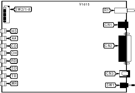
CONNECTIONS | |||
|
Purpose |
Location |
Purpose |
Location |
|
Line out |
CN1 |
Volume |
R1 |
|
RS-232/422 |
CN2 |
Power switch |
SW1 |
|
DC power |
CN3 | ||
|
USER CONFIGURABLE SETTINGS | ||
|
Settings |
Label |
Position |
|
í DTR forced high |
SW2/1 |
On |
|
DTR normal |
SW2/1 |
Off |
|
í Verbose result code enabled |
SW2/2 |
Off |
|
Verbose result code disabled |
SW2/2 |
On |
|
í Result codes enabled |
SW2/3 |
On |
|
Result codes disabled |
SW2/3 |
Off |
|
í Echo enabled |
SW2/4 |
Off |
|
Echo disabled |
SW2/4 |
On |
|
í Auto answer enabled |
SW2/5 |
Off |
|
Auto answer disabled |
SW2/5 |
On |
|
í CD forced high |
SW2/6 |
On |
|
CD normal |
SW2/6 |
Off |
|
í RJ11 jack selected |
SW2/7 |
Off |
|
RJ12/13 jack selected |
SW2/7 |
On |
|
í AT command set enabled |
SW2/8 |
On |
|
AT command set disabled |
SW2/8 |
Off |
|
DIAGNOSTIC LED(S) | |||
|
LED |
Color |
Status |
Condition |
|
HS |
Red |
On |
Modem is operating at 1200bps |
|
HS |
Red |
Off |
Modem is operating at slower than 1200bps |
|
AA |
Red |
On |
Auto-answer enabled |
|
AA |
Red |
Off |
Auto-answer disabled |
|
AA |
Red |
Blinking |
Phone is ringing |
|
CD |
Red |
On |
Carrier signal detected |
|
CD |
Red |
Off |
Carrier signal not detected |
|
OH |
Red |
On |
Modem is off-hook |
|
OH |
Red |
Off |
Modem is on-hook |
|
RD |
Red |
On |
Modem is receiving data |
|
RD |
Red |
Off |
Modem is not receiving data |
|
SD |
Red |
On |
Modem is transmitting data |
|
SD |
Red |
Off |
Modem is not transmitting data |
|
TR |
Red |
On |
DTR signal is high |
|
TR |
Red |
Off |
DTR signal is low |
|
MR |
Red |
On |
Power is on |
|
MR |
Red |
Off |
Power is off |
Proprietary AT Command Set
|
BIT-MAPPED REGISTER S13 | |||
|
Format |
AT [cmds] S13? [cmds] | ||
|
Default: |
Read-only | ||
|
Range: |
0-255 | ||
|
Unit: |
Bit-mapped | ||
|
Description: |
Displays basic/extended result codes , parity, and buffer overflow. | ||
|
Bit |
Value |
Function | |
|
0 |
0 |
Not used. | |
|
1 |
0 1 |
Basic result code enabled. Extended result code enabled. | |
|
2 |
0 1 |
Disable Parity. Enable Parity. | |
|
3 |
0 1 |
Odd Parity. Even Parity. | |
|
4 |
0 1 |
7 data bits. 8 data bits. | |
|
5 |
0 |
Not used. | |
|
6 |
0 1 |
Buffer overflow flag disabled. Buffer overflow flag enabled; ERROR is displayed. | |
|
7 |
0 1 |
Space Parity. Mark Parity. | |
|
BIT-MAPPED REGISTER S14 | |||
|
Format |
AT [cmds] S14? [cmds] | ||
|
Default: |
Read-only | ||
|
Range: |
0-255 | ||
|
Unit: |
Bit-mapped | ||
|
Description: |
Displays status of switch 5, echo, result codes and format, command recognition, dial option, and speaker options. | ||
|
Bit |
Value |
Function | |
|
0 |
0 1 |
Auto-answer disabled. Auto-answer enabled. | |
|
1 |
0 1 |
Disable local echo. Enable local echo. | |
|
2 |
0 1 |
Enable result codes. Disable result codes. | |
|
3 |
0 1 |
Numeric result code. Verbose result code. | |
|
4 |
0 1 |
Enable command recognition; switch 8 - On. Disable command recognition; switch 8 - Off. | |
|
5 |
0 1 |
Tone dial. Pulse dial. | |
|
6 |
0 1 |
Speaker off. Speaker off on carrier. | |
|
7 |
0 1 |
Speaker off. Speaker always on. | |
|
BIT-MAPPED REGISTER S15 | |||
|
Format |
AT [cmds] S15? [cmds] | ||
|
Default: |
Read-only | ||
|
Range: |
0-255 | ||
|
Unit: |
Bit-mapped | ||
|
Description: |
Displays data rate, answer/originate mode, and carrier signal. | ||
|
Bit |
Value |
Function | |
|
1, 0 |
00 01 10 11 |
Not used. 110bps. 300bps. 1200bps. | |
|
2 |
0 1 |
Answer mode. Originate mode. | |
|
3 |
0 1 |
Half duplex. Full duplex. | |
|
5, 4 |
00 01 10 11 |
Not used. 110bps. 300bps. 1200bps. | |
|
6 |
0 1 |
Carrier disabled. Carrier enabled. | |
|
TEST MODES | |
|
Type: |
Register |
|
Format: |
AT [cmds] S16=n [cmds] |
|
Description: |
Controls loopback tests; analog, digital, and self tests. |
|
Command |
Function |
|
S16=0 |
Normal mode. |
|
S16=1 |
Analog loopback test enabled. |
|
S16=2 |
DTMF tone test enabled. |
|
S16=4 |
Digital loopback test enabled. |