RAD DATA COMMUNICATIONS
ASMI-31 MODEM/IR-ETH
|
Card Type |
Modem |
|
Chip Set |
Unidentified |
|
I/O Options |
AC power connector, 15-pin connector, Network interface via terminal block and RJ-45 connector, Ethernet bridge |
|
Wiring Type |
RJ-45 shielded twisted pair Terminal block shielded twisted pair |
|
Maximum Data Rate |
128Kbps |
|
Line Coding |
2B1Q |
|
Data Bus |
External |
|
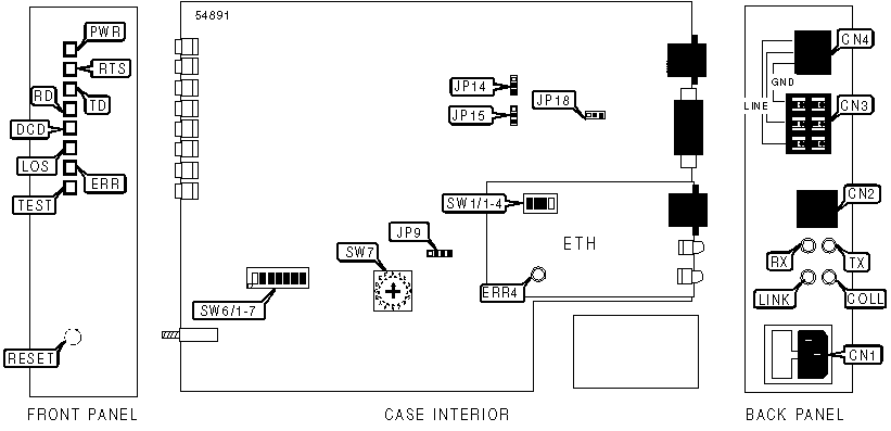
CONNECTIONS | ||||
|
Function |
Label |
Function |
Label | |
|
AC power connector |
CN1 |
Network interface via RJ-45 connector |
CN4 | |
|
Ethernet interface |
CN2 |
Reset push-button |
RESET | |
|
Network interface via terminal block |
CN3 | |||
|
Note: |
RJ-45 Ethernet connector is installed for use with 10BaseT networks. The ASMI-31 MODEM/IR-ETH is also available with a BNC connector for use with 10Base2 networks. | |||
|
USER CONFIGURABLE SETTINGS | ||
|
Setting |
Label |
Position |
|
í Loopback timing mode enabled |
JP9 |
Pins 3 & 4 closed |
|
Internal clock mode enabled |
JP9 |
Pins 2 & 3 closed |
|
External clock mode enabled |
JP9 |
Pins 1 & 2 closed |
|
í Remote digital DTE loopback test disabled |
JP14 |
Pins 1 & 2 closed |
|
Remote digital DTE loopback test enabled |
JP14 |
Pins 2 & 3 closed |
|
í Local analog DTE loopback test disabled |
JP15 |
Pins 1 & 2 closed |
|
Local analog DTE loopback test enabled |
JP15 |
Pins 2 & 3 closed |
|
í Signal ground is connected to the frame ground |
JP18 |
Pins 2 & 3 closed |
|
Signal ground is not connected to the frame ground |
JP18 |
Pins 1 & 2 closed |
|
í Factory configured - do not alter |
SW1/1 |
Off |
|
í Only frames destined for another LAN are transmitted over WAN |
SW1/2 |
On |
|
All frames are transmitted over WAN |
SW1/2 |
Off |
|
í Compression enabled |
SW1/3 |
On |
|
Compression disabled |
SW1/3 |
Off |
|
í WAN link is in synchronous mode |
SW1/4 |
Off |
|
WAN link is in asynchronous mode |
SW1/4 |
On |
|
í Synchronous operation mode enabled |
SW6/1 |
On |
|
Asynchronous operation mode enabled |
SW6/1 |
Off |
|
í 8-bit |
SW6/2 |
On |
|
7-bit |
SW6/2 |
Off |
|
í Parity enable |
SW6/3 |
On |
|
Parity disabled |
SW6/3 |
Off |
|
í Parity even |
SW6/4 |
On |
|
Parity odd |
SW6/4 |
Off |
|
í 1 stop bit |
SW6/5 |
On |
|
2 stop bits |
SW6/5 |
Off |
|
í DCD mode enabled |
SW6/6 |
On |
|
CNT mode enabled |
SW6/6 |
Off |
|
í DSR mode enabled |
SW6/7 |
On |
|
DTR mode enabled |
SW6/7 |
Off |
|
DATA RATE | ||||||
|
Setting |
Mode |
SW7 | ||||
|
1200bps |
Sync/async |
1 | ||||
|
2400bps |
Sync/async |
2 | ||||
|
4800bps | Sync/async |
3 | ||||
|
9600bps | Sync/async |
4 | ||||
|
19.2Kbps | Sync/async |
5 | ||||
|
38.4Kbps | Sync/async |
6 | ||||
|
48.0Kbps | Sync |
7 | ||||
|
í 64.0Kbps | Sync |
9 | ||||
|
128.0Kbps | Sync |
A | ||||
|
57.6Kbps | Async |
C | ||||
|
115.2Kbps | Async |
D | ||||
|
16Kbps | Unidentified |
E | ||||
|
32Kbps | Unidentified |
F | ||||
|
ASMI-31 DIAGNOSTIC LEDS | |||
|
LED |
Color |
Status |
Condition |
|
PWR |
Green |
On |
Power is on |
|
PWR |
Green |
Off |
Power is off |
TD |
Yellow |
On |
Device is transmitting a steady space |
TD |
Yellow |
Blinking |
Device is transmitting data |
|
TD |
Yellow |
Off |
Device is not transmitting data |
|
RD |
Yellow |
On |
Device is receiving a steady space |
|
RD |
Yellow |
Blinking |
Device is receiving pulses from network |
|
RD |
Yellow |
Off |
Device is not receiving pulses from network |
|
RTS |
Yellow |
On |
RTS signal is high |
|
RTS |
Yellow |
Off |
RTS signal is low |
|
DCD |
Yellow |
On |
DCD signal is high |
|
DCD |
Yellow |
Off |
DCD signal is low |
|
LOS |
Red |
On |
Loss of synchronization |
|
LOS |
Red |
Blinking |
Synchronization not established |
|
LOS |
Red |
Off |
Synchronization OK |
|
ERR |
Red |
On |
Error detected on received configuration information |
|
ERR |
Red |
Off |
Error not detected on received configuration information |
|
TST |
Red |
On |
Device is conducting a loopback test |
|
TST |
Red |
Off |
Device is not conducting a loopback test |
|
ETH BRIDGE DIAGNOSTIC LEDS | |||
|
LED |
Color |
Status |
Condition |
|
LINK |
Green |
On |
Ethernet network bridge is good |
|
LINK |
Green |
Off |
Ethernet network bridge is broken |
COLL |
Yellow |
On |
Collision has been detected on network |
COLL |
Yellow |
Off |
Collision has not been detected on network |
|
RX |
Yellow |
On |
Data is being received |
|
RX |
Yellow |
Off |
Data is not being received |
|
TX |
Yellow |
On |
Data is being transmitted |
|
TX |
Yellow |
Off |
Data is not being transmitted |
|
ERR |
Red |
On |
Error has been detected |
|
ERR |
Red |
Off |
Error has not been detected |