XIRCOM, INC.
MCI-23
|
Card Type |
ISDN DSU |
|
Chip Set |
Unidentified |
|
I/O options |
Unidentified |
|
ISDN Transfer Rate |
64Kbps x 23 |
|
Data Bus |
16-bit ISA |
|
Switch Type |
5ESS, DMS-100, MD-110 |
|
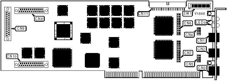
CONNECTIONS | |||
|
Function |
Label |
Function |
Label |
|
Line B out |
CN1 |
Used only on CSU/DSU model |
CN4-CN7 |
|
Line A out |
CN2 |
Daughterboard headers |
CN8-CN10 |
|
Diagnostic port |
CN3 |
MVIP bus - not used on this model |
CN11 |
|
BASE I/O ADDRESS | ||||||||||
|
Setting |
SW1/1 |
SW1/2 |
SW1/3 |
SW1/4 |
SW1/5 |
SW1/6 |
SW1/7 |
SW1/8 |
SW1/9 |
SW1/10 |
|
0000h |
On |
On |
On |
On |
On |
On |
On |
On |
On |
On |
|
0010h |
On |
On |
On |
On |
On |
On |
On |
On |
On |
Off |
|
0020h |
On |
On |
On |
On |
On |
On |
On |
On |
Off |
On |
|
0030h |
On |
On |
On |
On |
On |
On |
On |
On |
Off |
Off |
|
0040h |
On |
On |
On |
On |
On |
On |
On |
Off |
On |
On |
|
01E0h |
On |
On |
On |
On |
On |
Off |
Off |
Off |
Off |
On |
|
3FB0h |
Off |
Off |
Off |
Off |
Off |
Off |
Off |
On |
Off |
Off |
|
3FC0h |
Off |
Off |
Off |
Off |
Off |
Off |
Off |
Off |
On |
On |
|
3FD0h |
Off |
Off |
Off |
Off |
Off |
Off |
Off |
Off |
On |
Off |
|
3FE0h |
Off |
Off |
Off |
Off |
Off |
Off |
Off |
Off |
Off |
On |
|
3FF0h |
Off |
Off |
Off |
Off |
Off |
Off |
Off |
Off |
Off |
Off |
|
Note: A total of 1023 base address settings are available. The switches are a binary representation of the decimal memory addresses. SW1/1 is the Most Significant Bit and switch SW1/10 is the Least Significant Bit. The switches have the following decimal values: SW1/1=8192, SW1/2=4096, SW1/3=2048, SW1/4=1024, SW1/5=512, SW1/6=256, SW1/7=128, SW1/8=64, SW1/9=32, SW1/10=16. Turn off the switches and add the values of the switches that are off to obtain the correct memory address. (Off=1, On=0) | ||||||||||

|
DIAGNOSTIC LED(S) | |||
|
LED |
Color |
Status |
Condition |
|
LED1 |
Yellow |
On |
Carrier signal not detected on port A |
|
LED1 |
Yellow |
Off |
Carrier signal detected on port A |
|
LED2 |
Yellow |
On |
Carrier signal not detected on port B |
|
LED2 |
Yellow |
Off |
Carrier signal detected on port B |
|
LED3 |
Green |
On |
Board is active |
|
LED3 |
Green |
Off |
Board is not active |
|
LED4 |
Yellow |
On |
Board has failed |
|
LED4 |
Yellow |
Off |
Board is operating normally |