JUKO LABORATORIES, LTD.
G7-B
|
Category |
Video |
|
Video Types Supported |
Monochrome, CGA, EGA |
|
Video Processor |
Juko |
|
Highest Resolution Supported |
640 x 400 |
|
Data Bus Type |
8-bit ISA |
|
Memory Type |
DRAM |
|
Maximum Onboard Memory |
256KB (location unknown) |
|
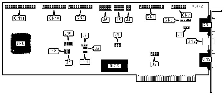
CONNECTIONS | |||
|
Purpose |
Location |
Purpose |
Location |
|
9-pin video port |
CN1 |
25-pin parallel port - internal |
CN8 |
|
Composite video jack |
CN2 |
25-pin serial port - internal |
CN9 |
|
9-pin mouse port |
CN3 |
25-pin serial port - internal |
CN10 |
|
6-pin light pen connector |
CN5 |
Control cable connector - floppy drive |
CN11 |
|
16-pin game port |
CN7 | ||
|
COMPOSITE COLOR DISPLAY CONFIGURATIONS | |||
|
Function |
Location |
Setting | |
| » |
Composite color selected |
J1 |
Pins 1 & 2 closed |
| » |
Clock frequency is 14.31818 MHz |
J3 |
Pins 1 & 2 closed |
|
J5/SW3 |
Pins 2 & 3 closed | ||
|
Composite color video mode selected |
J5/SW4 |
Pins 2 & 3 closed | |
|
J5/SW5 |
Pins 1 & 2 closed | ||
|
COMPOSITE MONOCHROME DISPLAY CONFIGURATIONS | |||
|
Function |
Location |
Setting | |
|
Composite mono selected |
J1 |
Pins 2 & 3 closed | |
| » |
Clock frequency is 14.31818 MHz |
J3 |
Pins 1 & 2 closed |
|
J5/SW3 |
Pins 2 & 3 closed | ||
|
Composite mono video mode selected |
J5/SW4 |
Pins 1 & 2 closed | |
|
J5/SW5 |
Pins 2 & 3 closed | ||
|
CGA DISPLAY CONFIGURATIONS | |||
|
Function |
Location |
Setting | |
| » |
Clock frequency is 14.31818 MHz |
J3 |
Pins 1 & 2 closed |
| » |
Vertical synchronize pulse is positive |
J5/SW1 |
Pins 1 & 2 closed |
| » |
Horizontal synchronize pulse is positive |
J5/SW2 |
Pins 1 & 2 closed |
|
J5/SW3 |
Pins 1 & 2 closed | ||
| » |
CGA display mode selected |
J5/SW4 |
Pins 2 & 3 closed |
|
J5/SW5 |
Pins 1 & 2 closed | ||
|
MONOCHROME DISPLAY CONFIGURATIONS | |||
|
Function |
Location |
Setting | |
|
Clock frequency is 16MHz |
J3 |
Pins 3 & 4 closed | |
|
Vertical synchronize pulse is negative |
J5/SW1 |
Pins 2 & 3 closed | |
| » |
Horizontal synchronize pulse is positive |
J5/SW2 |
Pins 1 & 2 closed |
|
J5/SW3 |
Pins 1 & 2 closed | ||
|
Mono display mode selected |
J5/SW4 |
Pins 1 & 2 closed | |
|
J5/SW5 |
Pins 1 & 2 closed | ||
|
640 X 400 COLOR DISPLAY CONFIGURATIONS | ||
|
Function |
Location |
Setting |
|
Clock frequency is 23.4MHz |
J3 |
Pins 5 & 6 closed |
|
Vertical synchronize pulse is negative |
J5/SW1 |
Pins 2 & 3 closed |
|
Horizontal synchronize pulse is negative |
J5/SW2 |
Pins 2 & 3 closed |
|
J5/SW3 |
Pins 1 & 2 closed | |
|
640 x 400 display mode selected |
J5/SW4 |
Pins 1 & 2 closed |
|
J5/SW5 |
Pins 2 & 3 closed | |
|
MOUSE PORT (CN3) INTERRUPT SELECTION | ||
|
Setting |
J2 | |
| » |
IRQ2 |
Pins 1 & 2 closed |
|
IRQ3 |
Pins 3 & 4 closed | |
|
IRQ4 |
Pins 5 & 6 closed | |
|
IRQ5 |
Pins 7 & 8 closed | |
|
MOUSE PORT MODE | ||
|
Setting |
J6/SW1 | |
| » |
Enabled |
Pins 1 & 2 closed |
|
Disabled |
Pins 2 & 3 closed | |
|
MOUSE PORT IRQ MATCHING | |||||
|
Setting |
J6/SW2 |
J6/SW3 |
J6/SW4 |
J6/SW5 | |
| » |
IRQ2 |
Pins 1 & 2 closed |
Pins 2 & 3 closed |
Pins 2 & 3 closed |
Pins 2 & 3 closed |
|
IRQ3 |
Pins 2 & 3 closed |
Pins 1 & 2 closed |
Pins 2 & 3 closed |
Pins 2 & 3 closed | |
|
IRQ4 |
Pins 2 & 3 closed |
Pins 2 & 3 closed |
Pins 1 & 2 closed |
Pins 2 & 3 closed | |
|
IRQ5 |
Pins 2 & 3 closed |
Pins 2 & 3 closed |
Pins 2 & 3 closed |
Pins 1 & 2 closed | |
|
PARALLEL PRINTER PORT (CN8) MODE | ||
|
Setting |
J4/SW1 | |
| » |
enabled |
Pins 1 & 2 closed |
|
Disabled |
Pins 2 & 3 closed | |
|
GAME PORT (CN7) MODE | ||
|
Setting |
J4/SW2 | |
| » |
Enabled |
Pins 1 & 2 closed |
|
Disabled |
Pins 2 & 3 closed | |
|
REALTIME CLOCK CONFIGURATIONS | |||
|
Function |
Location |
Setting | |
| » |
Clock assigned as timer 1 (340-35F) |
J7 |
Pins 1& 2 closed |
|
Clock assigned as timer 2 (240-25F) |
J7 |
Pins 2 & 3 closed | |
| » |
Timer uses IRQ4 |
J10 |
Pins 1 & 2 closed |
|
Timer uses IRQ4 |
J10 |
Pins 3 & 4 closed | |
|
Timer uses IRQ4 |
J10 |
Pins 5 & 6 closed | |
|
Timer uses IRQ4 |
J10 |
Pins 7 & 8 closed | |
|
SERIAL PORT 2 (CN9) CONFIGURATION | ||
|
ADDRESS/IRQ |
J8 |
J9 |
|
2F8-2FF/IRQ4 |
Closed |
Closed |
|
Port disabled |
Open |
Open |
|
SERIAL PORT 1 (CN10) CONFIGURATION | ||
|
ADDRESS/IRQ |
J11 |
J12 |
|
3F8-3FF/IRQ4 |
Closed |
Closed |
|
Port disabled |
Open |
Open |